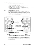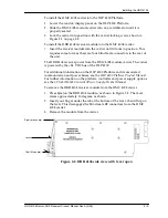
Installing the HRR 4104 Receiver
2–4
Copyright © 2005 Harmonic Inc.
2.4
Con
fi
guring Two HRR 4104 Modules as a
Redundant Pair
Each HRR 4104 module can be configured in one of the following ways:
•
As an independent, standalone module (not connected to another
module)
•
As the primary module in a redundant pair (connected to a backup
module)
•
As the backup module in a redundant pair (connected to a primary
module)
This section provides instructions for configuring the HRR 4104 modules
as redundant pairs. If you are configuring the HRR 4104 to operate as an
independent module, you can skip this section.
Regardless of configuration, all four receivers in a module function in the
same role; all four receivers are standalone, primary, or backup. However, at
any given time, some receivers in a module can be muted (inactive) while
others are not.
In a redundant pair configuration, you use one module for primary fiber
paths and a second module for backup fiber paths. Normally, the primary
receiver mutes the RF output of the backup receiver. If the primary receiver is
in alarm (the optical input level on the primary receiver falls below a set
threshold: the optical alarm limit), the primary receiver activates (unmutes)
the backup receiver and mutes itself (unless the backup receiver’s optical
input level is also low, in which case the backup receiver remains muted).
When the primary receiver’s optical input level rises above the optical alarm
limit, it removes the
unmute
command from the backup receiver and the
backup receiver returns to its default muted state.
When configuring a redundant pair, Harmonic recommends locating the two
HRR 4104 modules in two different HLP 4200 Platforms, if possible. That way,
transmission continues even if there is problem with a platform or power
supply.
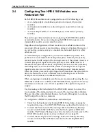
Use the muting cable (included with the HMC 4008 carrier) to connect the
two modules of the redundant pair. One end of the muting cable is labeled
Primary, the other end is labeled Backup. Use four 4 dB couplers to combine
the RF output from the two modules.
To configure two HRR 4104 modules as a redundant pair:
1. Verify that both primary and backup HRR 4104 modules are properly
mounted into one or two HLP 4200 Platforms, as described in Section 2.3.
2. Connect the Primary end of the muting cable to the Primary/Backup
connector of the HMC 4008 that is attached to the primary HRR 4104
module. The Primary/Backup connector is located on the rear panel of the
HMC 4008 module carrier, as shown in Figure 2-1 on page 2-2.
3. Connect the Backup end of the muting cable to the Primary/Backup
connector of the HMC 4008 that is attached to the backup HRR 4104
module.
Summary of Contents for HRR 4104
Page 1: ...HRR 4104 Return Path Receiver Product Manual Manual Part No 700 0051981 Rev A March 2005...
Page 8: ...Overview 1 4 Copyright 2005 Harmonic Inc...
Page 36: ...Maintenance and Troubleshooting 5 6 Copyright 2005 Harmonic Inc...
Page 40: ...Technical Specifications A 4 Copyright 2005 Harmonic Inc...
Page 42: ...Harmonic Inc Offices B 2 Copyright 2005 Harmonic Inc...

