Installing the HRR 4104 Receiver
2–6
Copyright © 2005 Harmonic Inc.
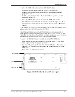
5. Connect the fiber to the correct optical connector on the front of the
HRR 4104 according to the instructions in section
6. The fiber naturally forms a service loop that fits behind the protective
front plate on the fiber tray, as shown in Figure 2-5 on page 2-7. The fiber
should run straight through the channel and hang out the back of the tray.
At the rear of the HRR 4104 modules, additional fiber management or routing
may be required.
Figure 2-3. HFM 4000 Fiber Management Tray
Figure 2-4. HFM 4000 below HLP 4200
fully loaded with HRR 4104 modules
Summary of Contents for HRR 4104
Page 1: ...HRR 4104 Return Path Receiver Product Manual Manual Part No 700 0051981 Rev A March 2005...
Page 8: ...Overview 1 4 Copyright 2005 Harmonic Inc...
Page 36: ...Maintenance and Troubleshooting 5 6 Copyright 2005 Harmonic Inc...
Page 40: ...Technical Specifications A 4 Copyright 2005 Harmonic Inc...
Page 42: ...Harmonic Inc Offices B 2 Copyright 2005 Harmonic Inc...

