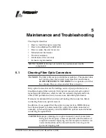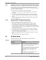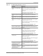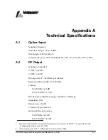
Technical Speci
fi
cations
A–2
Copyright © 2005 Harmonic Inc.
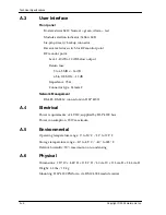
A.3 User
Interface
Front panel
Bi-state status LED: Normal = green, Alarm = red
Module selection indicator: Yellow LED
Six-pin primary/backup connector
Receiver selector switch for RF monitor point
RF monitor point:
Level: –20 dB ±1.0 dB below output
Return loss:
5 to 65 MHz: –16 dB
65 to 100 MHz: –12 dB
Impedance: 75
Ω
Connector type: Female F
Network Management
RS-485, RS-233C connectors (in HLP 4200)
A.4 Electrical
Power requirements: +24 VDC; supplied by HLP 4200 bus
Power consumption: 15 W maximum
A.5 Environmental
Operating temperature range: 0° to 50° C / 32° to 122° F
Storage temperature range: –40° to 85° C / –40° to 185° F
Relative humidity: 90% maximum, non-condensing
A.6 Physical
Dimensions: 1.20" W x 4.45" H x 11.53" D / 3.0 cm W x 11.3 cm H x 24.3 cm D
Weight: 3.3 lbs / 1.5 kg
Mounting: HLP 4200 Platform; via HMC 4008 module carrier
Summary of Contents for HRR 4104
Page 1: ...HRR 4104 Return Path Receiver Product Manual Manual Part No 700 0051981 Rev A March 2005...
Page 8: ...Overview 1 4 Copyright 2005 Harmonic Inc...
Page 36: ...Maintenance and Troubleshooting 5 6 Copyright 2005 Harmonic Inc...
Page 40: ...Technical Specifications A 4 Copyright 2005 Harmonic Inc...
Page 42: ...Harmonic Inc Offices B 2 Copyright 2005 Harmonic Inc...

