Connecting the RF Output Cables
HRR 4104 Return Path Receiver Product Manual Rev A (3/05)
2–5
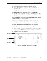
4. Connect a 4 dB coupler between the two Receiver A outputs of the
HMC 4008 module carriers that are attached to the two HRR 4104
modules. The RF output connectors are located on the rear panel of the
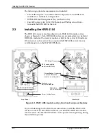
HMC 4008 module carrier, as shown in Figure 2-1 on page 2-2.
5. Connect three more 4 dB couplers between the two Receiver B outputs,
the two Receiver C outputs, and the two Receiver D outputs.
2.5
Connecting the RF Output Cables
The HRR 4104 has four RF output connectors, which are located on the rear
panel of the HMC 4008 carrier, as shown in Figure 2-1 on page 2-2. They are
labelled
A
,
B
,
C
, and
D
. They are female F connectors that accept 75 Ohm
impedance coaxial cables terminated with male F connectors.
NOTE:
To ensure performance integrity, use RG-59 coaxial cable.
To connect the RF output cables:
1. Verify that the HRR 4104 is properly mounted into the HLP 4200 Platform,
2. Connect the male F connectors of the coaxial cables to the RF output
connectors on the rear panel of the HMC 4008 carrier. Or, if couplers are
attached (as described in Section 2.4), connect the cables to the couplers.
3. Tighten the cables securely (using an F-connector tool, if necessary).
2.6
Installing and Using the HFM 4000 Fiber
Management Tray
The HFM 4000 Fiber Management Tray (shown in Figure 2-3 on page 2-6) is
an optional accessory for the HRR 4104. It is a 1 rack-unit tray designed to sit
directly below the HLP 4200 Platform and route the fibers from the modules
to the rear of the rack, as shown in Figure 2-4 on page 2-6.
To mount the HFM 4000 in the rack, you need:
•
Four #10 screws with 10-24 UNC thread
•
Phillips screwdriver
To install and use the HFM 4000 Fiber Management Tray in a standard
equipment rack:
1. Mark the exact position in the rack where you want to install the tray.
The rack works best when it is located directly below the HLP 4200
Platform that houses the HRR 4104 modules.
2. Position the tray in the rack, align the holes in the mounting brackets of
the HFM 4000 with the threaded holes in the rack upright, then secure the
four mounting screws through the mounting brackets.
3. Identify and mark each fiber before routing fibers into the HFM 4000.
4. Route each fiber through the appropriate fiber channel of the HFM 4000.
The HFM 4000 has fiber channels for each slot of the HLP 4200 Platform.
Fibers can be routed from the front or rear.
Summary of Contents for HRR 4104
Page 1: ...HRR 4104 Return Path Receiver Product Manual Manual Part No 700 0051981 Rev A March 2005...
Page 8: ...Overview 1 4 Copyright 2005 Harmonic Inc...
Page 36: ...Maintenance and Troubleshooting 5 6 Copyright 2005 Harmonic Inc...
Page 40: ...Technical Specifications A 4 Copyright 2005 Harmonic Inc...
Page 42: ...Harmonic Inc Offices B 2 Copyright 2005 Harmonic Inc...

