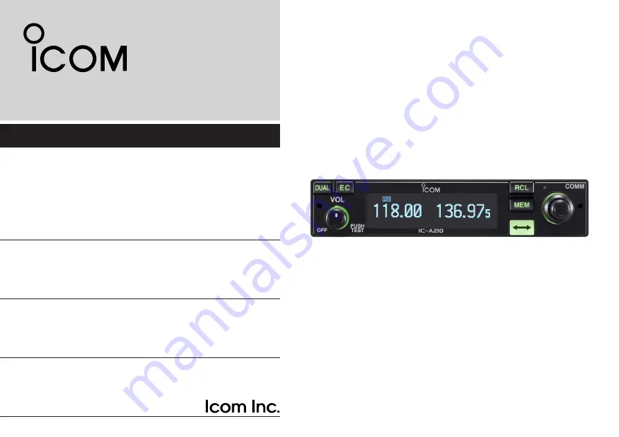
iA210
VHF AIR BAND TRANSCEIVER
INSTRUCTION MANUAL
This device complies with Part 15 of the FCC Rules. Operation is subject to the condition that this device does not cause harmful interference.
Page 1: ...iA210 VHF AIR BAND TRANSCEIVER INSTRUCTION MANUAL This device complies with Part 15 of the FCC Rules Operation is subject to the condition that this device does not cause harmful interference...
Page 2: ...The flip flop arrow button switches between active and standby channels The DualWatch function allows you to monitor two channels simultaneously In addition the history memory chan nel stores the las...
Page 3: ...nst continuous high volume op eration If you experience a ringing in your ears reduce the volume level or discontinue use R WARNING NEVER connect the transceiver to an AC outlet or to a power source o...
Page 4: ...ory channel only 15 Programming group names Group memory channel only 15 Programming channel tag Group memory channel only 16 Channel tag list 16 Weather memory channel U S A version only 17 GPS memor...
Page 5: ...121 5 MHz p 19 e VOLUME POWER SWITCH VOL Turn VOL to switch the power ON or OFF p 5 Adjusts the audio output level The volume level bar appears while rotating VOL Push to set the squelch test functio...
Page 6: ...ht The detector is used to adjust Dimmer brightness Low High p 25 auto matically when the Dimmer Mode p 25 is set to AUTO i INNER Small TUNING DIAL DIAL Rotate to set the standby frequencies kHz digit...
Page 7: ...for details 1 Ask your dealer for available GPS receiver details Main unit q Metal catch For Icom products Use to attach to an installation rack for Icom products Refer to the INSTALLATION GUIDE for...
Page 8: ...group memory channel is selected p 13 The group name is also indicated if the name has been entered Indicates HISTORY when the history memory chan nel is selected p 14 Indicates WEATHER when the weat...
Page 9: ...de operation Standby frequency selection Step 1 2 q Rotate VOL clockwise to turn power ON Previously used frequencies appear in the active and standby frequency indicators w Rotate DIAL and O DIAL to...
Page 10: ...etails RX appears when receiving a signal or opening squelch w Push VOL to open the squelch manually Refer to page 20 Squelch test function for details e Rotate the volume control to adjust the audio...
Page 11: ...Rotate the large tuning dial to change the standby frequency in MHz steps Rotate the small tuning dial to change the standby frequency in kHz steps 121 805 134 80 RX 126 805 134 80 RX 126 405 134 80...
Page 12: ...at certain intervals even when receiving a signal on the standby frequency When a signal is received on the active frequency the radio switches to the active frequency and stays on it until the signal...
Page 13: ...lar memory channel MEMORY There are up to 10 available memory channels Group memory channel GRP01 GRP20 There are up to 200 group channels with 10 channels in each of 20 groups Weather memory channel...
Page 14: ...ush RCL to exit the memory mode Channel selection The transceiver has 10 channels in regular memory and 200 channels in the group memory There are 10 channels in each of 20 groups GRP01 GRP20 q Push R...
Page 15: ...05 134 80 RX MEMORY Set a 126 000 MHz in the standby display q Push RCL then rotate O DIAL to select MEMORY w Push MEM then rotate O DIAL to select REPLACE r Push MEM to store the desired frequency in...
Page 16: ...ory channel frequency into the active frequency display The memory mode is then cancelled automatically Memory mode menu Regular and group memory channels only REPLACE Replacing the standby frequency...
Page 17: ...nnel number appears The memory channel name also appears if it has been entered w Rotate O DIAL to select the group memory channel number A group number GRP01 GRP20 appears e Push DIAL and then rotate...
Page 18: ...Clearing the memory contents Regular and group memory channels only Unwanted memory channels can be cleared q Push RCL to select memory mode The channel number appears The memory channel name also app...
Page 19: ...Programming group names Group memory channel only The memory groups can display a six character name in ad dition to the group number GRP01 GRP20 q Push RCL then rotate O DIAL to select a desired memo...
Page 20: ...s selectable r Push MEM to set the channel tag Selectable tags ___ TWR GND ATS ATF APP ARR AWS CLR CTF DEP FSS RFS UNI MF OTH U 1 U 2 Channel tag list 1Group memory 2GPS memory CH01 127 005 122 00 RX...
Page 21: ...ion has VHF marine WX weather channel receiving capability for flight planning q Push RCL to enter the memory mode The channel number appears w Rotate O DIAL to select the weather memory channel WEATH...
Page 22: ...GPS memory channel edit mode then rotate O DIAL to select a desired group memory GPS and airport code blink r Push MEM to store the GPS memory channel data to the selected group memory t Push RCL to e...
Page 23: ...r the DualWatch operation automati cally w Push to transfer emergency frequency to the active frequency if necessary EC appears e Push to exit from the emergency frequency Set the frequency except 121...
Page 24: ...ith VOL in the MENU mode p 23 The microphone1 and microphone2 audio input levels can be also selected OFF or output level fixing 001 to 080 in the MENU mode p 23 Squelch test function This function op...
Page 25: ...is available for the U S A version only q Set to the weather memory channel mode w Hold down VOL for 2 seconds to start weather memory channel scan To change the scan direction turn DIAL NO WTH appea...
Page 26: ...L to exit MENU mode and returning to the pre vious operating mode MENU mode items MENU MODE SQL LEVEL 010 01 33 RCL MEM OFF VOL PUSH TEST COMM DUAL EC iA210 010 009 009 010 Desired condition setting S...
Page 27: ...Audio Input Level INCOM LV1 Set the intercom1 microphone input level OFF 0 Mutes the intercom1 microphone 001 to 080 Sets the intercom1 input level from 1 to 80 D Intercom2 Microphone Audio Input Leve...
Page 28: ...WATCH Set the active frequency receive interval time while receiving the standby frequency FAST Sets the interval time to 400 milliseconds MID Sets the interval time to 800 milliseconds SLOW Sets the...
Page 29: ...IC1 2 Selects both microphone1 and microphone2 D Dimmer Mode DISP MODE The light sensor which is built into the display is used for this function Set the OLED dimmer mode OFF The dimmer function is OF...
Page 30: ...AL to select the next input digit r Repeat w e to input the U 1 ID t Push MEM again to store the U 1 ID and exit the edit mode D USER 2 Setting U 2 ID SET Set the USER 2 channel tag to a desired ID q...
Page 31: ...0 seconds in 10 secons intervals D Frequency Step FREQ STEP Set the desired frequency step 8 33 kHz or 25 kHz 25kHz Setting the frequency step to 25 kHz 8 33kHz Setting the frequency step to 8 33 kHz...
Page 32: ...connect with the data jack Consult the CS A210 instruction manual and HELP file for details D Displayed Message While clone writing When clone writing is finished properly When clone writing error oc...
Page 33: ...Provides convenient operation of the transceiver on the ground A built in speaker and microphone are included Depending on version NOTE PS 80 s specifications Dimensions 200 W 200 H 300 D mm 7 9 W 7 9...
Page 34: ...approximately 1 0 kg 2 2 lb 1 U S A version only receiving only 2 U S A version only D Transmitter Mode AM Output power 8 W Carrier power Spurious emissions 60 dBc Microphone impedance 600 Modulation...
Page 35: ...erating Frequency MHz Channel spacing kHz Channel ID Displayed Frequency 118 0000 8 33 118 005 118 0083 8 33 118 010 118 0167 8 33 118 015 118 0250 8 33 118 030 118 0333 8 33 118 035 118 0417 8 33 118...
Page 36: ...t be mounted at least 36 centimeters away from the nearest edge of the vehicle in order to protect against exposure to bystanders To ensure that your exposure to RF elec tromagnetic energy is within t...
Page 37: ...ssurer que votre exposition une nergie lectromagn tique de RF se situe dans les limites permises par la FCC pour une utilisation grand public veuillez en tout temps respecter les directives suivantes...
Page 38: ...nterfer ence to radio communications However there is no guaran tee that interference will not occur in a particular installation If this equipment does cause harmful interference to radio or televisi...
Page 39: ...hone level 23 History memory channel 9 14 I Intercom function 20 Intercom usable setting 27 Intercom1 Microphone audio input level 23 Intercom1 squelch level 23 Intercom2 Microphone audio input level...
Page 40: ...A 6602H 1EX y Printed in Japan 2007 2011 Icom Inc Printed on recycled paper with soy ink 1 1 32 Kamiminami Hirano ku Osaka 547 0003 Japan...