


Kg m
•
N m
•
1
2
3
4
5
6
7
8
9
10
11
12
13
14
15
4.5~5.5
3.5~5.5
2.5~3.5
4.8~5.76
1.5~2.0
3.5~4.5
2.5~3.5
2.0~3.0
1.8~2.8
4.8~5.8
0.6~0.8
0.7~1.0
4.0~5.0
1.0~1.6
1.8~2.8
1.0~1.35
45.0~55.0
35.0~55.0
25.0~35.0
48.0~57.6
15.0~20.0
35.0~45.0
25.0~35.0
20.0~30.0
18.0~28.0
48.0~58.0
6.0~8.0
7.0~10.0
40.0~50.0
10.0~16.0
18.0~28.0
10.0~13.5
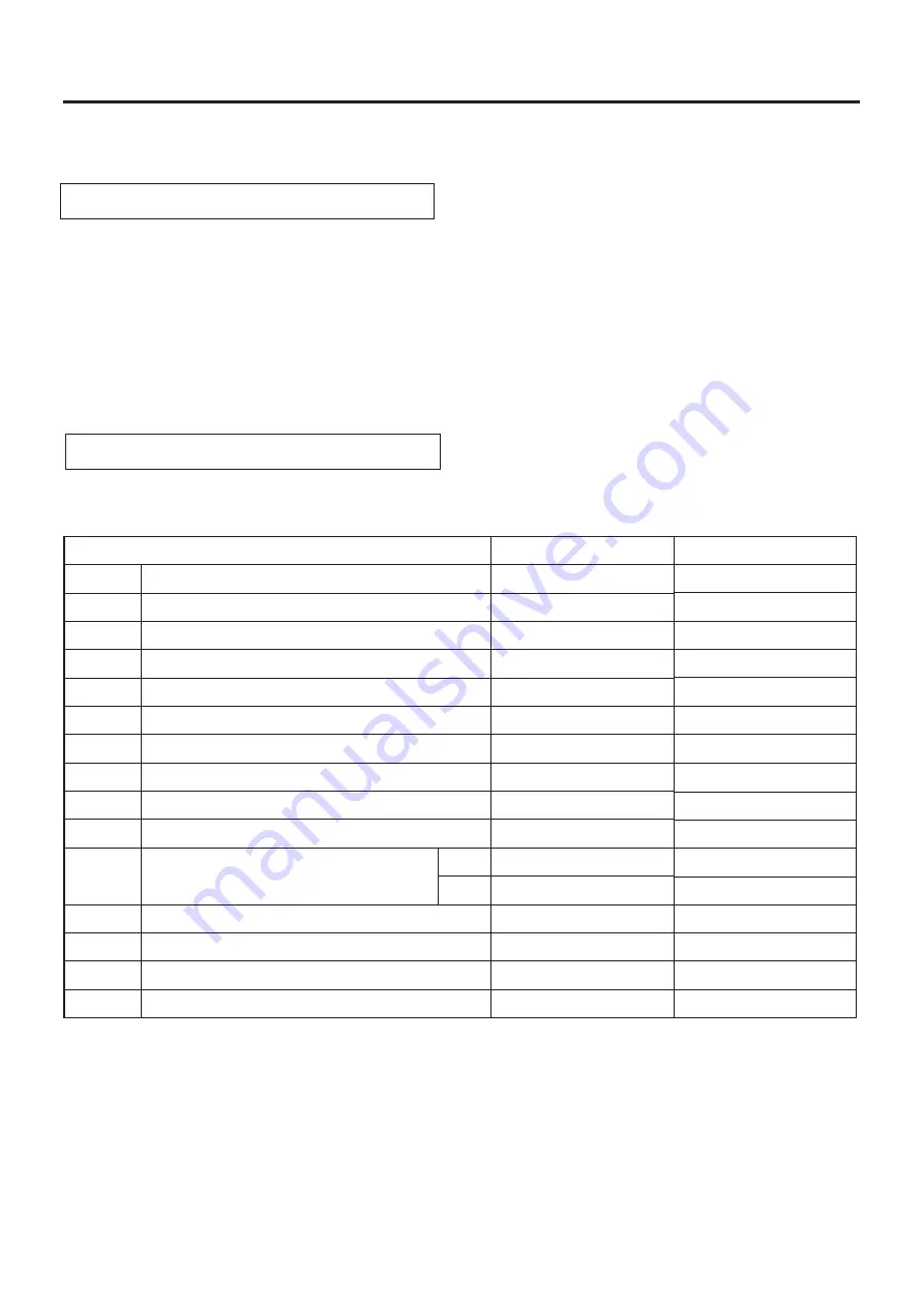
Inspect at Initial 1,000 km and Every 3,000 km
Check the tightening torque of the bolts and nuts for the motorcycle according to the table below:
CHASSIS AND ENGINE MOUNTING BOLTS AND NUTS
Kick starter bolt
Rear sprocket nut
Torque link bolt/nut
Hub assy nut
Brake cam lever bolt/nut
F
R
Rear axle nut
Rear footrest bolt
Rear absorber nut
Rear swing pivot nut
Engine mounting bolt/nut
Front footrest bolt
Front axle nut
Steering lock nut
Front absorber lock bolt
Handlebar lock bolt/nut
ITEM
PERIODIC MAINTENANCE
2 - 1 7
LIGHTS AND SIGNAL LIGHTS
Inspect at Initial 1,000 km and Every 3,000 km
Check all the lights and signal lights that must be correct.
Refer to page 6-8 and page 6-9.
https://www.motomanuals.net/


