44
Vol. 2.6 © 2020 Hanbell Precise Machinery Co., Ltd. All rights reserved
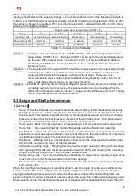
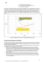
When adjusting the compressor towards the target water temperature, as IGV1 opening is not
linearly proportional to the capacity change, it is recommended to refer to the following example in
Table 3.4 for IGV1 adjustment range. Generally, when IGV opening is adjusted from 100% to 40%,
the capacity change is only about 21%, but when the opening is adjusted from 40% to 10%, there
will be a 34% capacity change.
Target chilled water temperature (CHWT), 7
℃
Range
<
6
℃
6~6.7
℃
7±0.3
℃
7.3~8
℃
>
8
℃
Loading mode
fast unloading normal unloading
Neutral zone
normal loading
fast loading
When IGV
≧
40%
IGV-10%
IGV-5%
no action
IGV+5%
IGV+10%
When IGV
<
40%
IGV-5%
IGV-3%
no action
IGV+3%
IGV+5%
Table 3.4 Capacity control table
Caution
:
1. Although under standard condition (CT/ET=36/6
℃)
, the typical target chilled water
temperature (CHWT) is 7
℃
, the target CHWT can be set to the desired temperature
by the user. If the neutral zone is too small (<±0.3
℃
), it can be difficult to obtain a
stable target CHWT. The reason for this issue is due to the deadband of actuator
being set to 2%.
Caution
:
2. The adjustment for the target CHWT should be mainly based on the input signal as the
output signal is often susceptible to noise and harmonic interference which could
cause significant deviation between output and input signal. Therefore, it is
recommended to cancel output signal feedback during capacity control, which can
also avoids heavy duty cycle due to feedback “hunting”.
Caution
:
3. Each IGV1 opening has a corresponding limit pressure ratio. During the loading and
unloading capacity control process, the pressure ratio must be monitored that it's
within the limit pressure ratio to ensure no surge occurred. Please refer to 3.3.1 safety
margin formula section for more information.
3.3 Surge and Stall phenomenon
【
Definition
】
】
】
】
Surge: When the flow rate continues to decrease after stalling, further breakdown of steady
through flow will occur which ultimately, leads to complete expansion of separation zone in
the flow path. This results in significant drop in discharge pressure and when the discharge
pressure is lower than the backpressure, reversal of flow will take place. Such phenomena
are periodic and detrimental due to heavy vibrations of compressor.
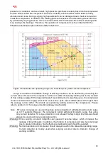
Surge point
:
Each IGV opening has a corresponding maximum pressure ratio surge point.
Surge line
:
The curve formed by connecting surge points of each IGV opening.
Stall: When the flow rate decreases, the incidence angle increases, causing more severe flow
separation as well as larger separation zone and at this point, the performance of compressor
is significantly deteriorated. This phenomenon is known as stalling.
Stall zone
:
Rotating stall is a local disruption of flow within the compressor at low flow rates
which limits the operating range of the compressor.
Allowable operating range
:
Ranging from the maximum IGV opening (100%) to the smallest
IGV opening (10%),with the maximum operation load of (105%) and covering the operating
range from safety margin line to the minimum pressure ratio.
Safety margin line
:
The curve is formed by translating the surge line to a safety margin at the
maximum upper limit of pressure ratio for each IGV opening.
Pressure ratio
:
Pressure ratio is the absolute pressure ratio between compressor discharge
and suction inlet.
When the centrifugal compressor is operating at part load, the angle of guide vanes will become
smaller, and the flow rate of refrigerant entering the compressor will also become smaller. The
surging and stalling phenomena occur when the flow rate is reduced beyond a critical limit. As
shown in Figure 3.5, when compressor operates above the surge line, stalling or surging may occur.
When surging occurs, the discharge pressure of compressor will reduce drastically, lower than the


