42
Vol. 2.6 © 2020 Hanbell Precise Machinery Co., Ltd. All rights reserved
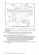
Figure3.4.1 Actuator2 Wiring Figure (for IGV2)
1.
Input signal #10(+ve) & #11(-ve)
:
4~20mA DC,0~5V DC,0~10V DC,1~5V DC
,
Factory setting
is 4-20mA DC
Output signal #12(+ve) & #13(-ve)
:
4~20mA DC,0~5V DC,0~10V DC,1~5V DC
,
Factory setting
is 4-20mA DC
2.
Power connecting point(220V AC 1PH,50/60Hz) #4 & #5
:
Note
:
Actuator 2 is used in heat pump models and T series (dual IGV), not for standard compressor
models.
3.2.6 LED indicator lights
LED
Indication
Blue light
Power on
Flickering
Blue light
Auto calibrating
Green light
Fully closed
Flickering
Green light
Closing
Red light
Fully open
Flickering
Red light
Opening
Yellow light
Manual mode
Flickering
Yellow light
Error indicator for one of the
following situations :
No input signal;
4-20 mA polarity error;
Reversal of equipotential line.
Table 3.2.6 LED Indicator lights


