41
Vol. 2.6 © 2020 Hanbell Precise Machinery Co., Ltd. All rights reserved
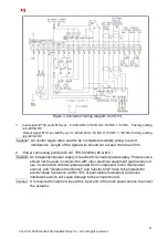
Figure 3.4 Actuator1 wiring diagram (for IGV1)
1.
Input signal #15(+ve) & #16(-ve)
:
4~20mA DC,0~5V DC,0~10V DC,1~5V DC
,
Factory setting
is 4-20mA DC
Output signal #17(+ve) & #18(-ve)
:
4~20mA DC,0~5V DC,0~10V DC,1~5V DC
,
Factory setting
is 4-20mA DC
Caution
:
All control signal wires need to be in shielded (isolated) wiring to avoid
interference. Length of the signal wire should not exceed more than 30m.
2
Power connecting point (220V AC 1PH,50/60Hz) #5 & #13
:
Caution
:
An independent power supply is required for actuator power supply. Power source
should not be used in conjunction with other electrical equipment (particularly not
use in connection with two-phase power from compressor motor main power
source), and "isolation transformer" and "electric filter" have to be installed to
avoid voltage fluctuation (within 10% of permissible fluctuation) and noise
interference which will cause damage to the actuator board.
Caution
:
It is required to install 2A fuse at the input end of the main power source to protect
the actuator.


