


15
Subject to change without notice
Automatic Peak (value) - Triggering
If the
AT/NM
pushbutton is in the out position
AT
, the sweep
generator is running without test signal or external trigger voltage.
A base line is always displayed even without a signal applied.
In automatic trigger mode the sweep generator can run without
test signal or external trigger voltage. A base line will always be
displayed even with no signal. With an applied
AC
signal the
peak value triggering enables the user to select the voltage
point on the trigger signal (trigger point), by the adjustment of
the trigger
LEVEL
control. The control range depends on the
peak to peak value of the signal. This trigger mode is therefore
called
Automatic Peak (Value)- Triggering
. Operation of the
scope needs only correct amplitude and time base settings, for
a constantly visible trace. Automatic mode is recommended for
all uncomplicated measuring tasks. However, automatic
triggering is also the appropriate operation mode for the “entry”
into difficult measuring problems, e.g. when the test signal is
unknown relating to amplitude, frequency or shape. Presenting
of all parameters is now possible with automatic triggering; the
change to normal triggering can follow thereafter.
The automatic triggering works above 20Hz. The failure of
automatic triggering at frequencies below 20Hz is abrupt.
However, it is not signified by the trigger indicator LED this is still
blinking. Break down of triggering is best recognizable at the left
screen edge (the start of the trace in differing display height).
The automatic peak (value) triggering operates over all variations
or fluctuations of the test signal above 20Hz. However, if the
pulse duty factor of a square-wave signal exceeds a ratio of
100:1, switching over to normal triggering will be necessary.
Automatic triggering is practicable with internal and external
trigger voltage.
Normal Triggering
With normal triggering (
AT/NM
button depressed) the sweep
can be started by
AC
signals within the frequency range
defined by the
TRIG. MODE
(trigger
coupling) setting.
In the absence of an adequate trigger signal or when the trigger
controls (particularly the LEVEL control) are misadjusted, no
trace is visible, i.e. the screen blanked completely.
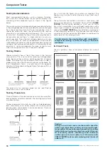
When using the internal normal triggering mode, it is possible
to trigger at any amplitude point of a signal edge, even with very
complex signal shapes, by adjusting the
LEVEL
control. Its
adjusting range is directly dependent on the display height,
which should be at least
0.5div.
If it is smaller than 1div., the
LEVEL
adjustment needs to be operated with a sensitive
touch. In the external normal triggering mode, the same applies
to approx. 0.3Vpp external trigger voltage amplitude.
Other measures for triggering of very complex signals are the
use of the time base variable control and
HOLDOFF
time control,
hereinafter mentioned.
Slope
The time base generator can be started by a rising or falling edge
of the test signal. This is valid with automatic and with normal
triggering. The selected slope is set with the
SLOPE (
)
pushbutton. The
/
sign (button released) means an edge, which
is coming from a negative potential and rising to a positive
potential. That has nothing to do with zero or ground potential
and absolute voltage values. The positive slope may also lie in a
negative part of a signal. A falling edge (
\
sign) triggers, when the
SLOPE (
)
pushbutton is depressed.
However the trigger point may be varied within certain limits on
the chosen edge using the
LEVEL
control. The slope direction is
always related to the input signal and the non inverted display.
.
Trigger coupling
The coupling mode and accordingly the frequency range of the
trigger signal can be changed using the
TRIG.
MODE
selector
switch.
AC:
Trigger range
<20Hz to 100MHz
.
This is the most frequently used trigger mode. The trigger
threshold is increasing below 20Hz and above 100MHz.
DC:
Trigger range
DC to 100MHz
.
DC triggering is recommended, if the signal is to be triggered
with quite slow processes or if pulse signals with constantly
changing pulse duty factors have to be displayed.
With DC- or LF-trigger coupling, always work with normal
triggering and LEVEL adjustment.
LF:
Trigger range
DC to 1.5kHz
(low-pass filter).
The LF position is often more suited for low-frequency
signals than the DC position, because the (white) noise in
the trigger voltage is strongly suppressed. So jitter or
double-triggering of complex signals is avoidable or at least
reduced, in particular with very low input voltages. The
trigger threshold increases above 1.5kHz.
TV:
The built-in
active TV-Sync-Separator
enables the
separation of sync pulses from the video signal. Even
distorted video signals are triggered and displayed in a
stable manner.
Video signals are triggered in the automatic mode. The
internal triggering is virtually independent of the display
height, but the sync pulse must exceed 0.5div. height. For
TV sync pulse separation the
TRIG. MODE
switch must be
set to
TV
. The
TIME/DIV
.-switch selects between
field
(
0.2s/div. - 1ms/div
.) and
line
(
0.5ms/div. - 0.1µs/div.
).
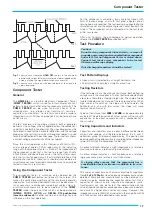
The slope of the leading edge of the synchronization pulse is
critical for the
SLOPE
pushbutton setting. If the displayed sync
pulses are
above
the picture (field) contents, then the
SLOPE
pushbutton (
) must be in
/
position (out). In the case of sync
pulses
below
the field/line, the leading edge is negative and the
SLOPE
pushbutton must therefore be depressed (to ”
\
”). Since
the
INV.
(invert) function may cause a misleading display, it must
not be activated until after correct triggering is achieved.
On the 2ms/div setting field TV triggering is selected and 1 field
is visible if a 50 fields/s signal is applied. If the holdoff control is
in fully ccw position, it triggers without line interlacing affects
caused by the consecutive field. More details in the video signal
become visible if the
X-MAG. x10
pushbutton is depressed (in).
The
X-POS
. control allows to display any part of the expanded
signal. The influence of the integrating network which forms a
trigger pulse from the vertical sync pulses may become visible
under certain conditions.
Disconnecting the trigger circuit (e.g. by rapidly pressing and
releasing the
TRIG. EXT.
button) can result in triggering the
consecutive (
odd
or
even
) field.
On the 10µs/div setting line TV triggering is selected and approx.
1
½
lines are visible. Those lines originate randomly from the odd
and even fields.
The sync-separator-circuit also operates with external triggering.
It is important that the voltage range (0.3V
pp
to 3V
pp
) for external
Triggering and time base


