


17
Subject to change without notice
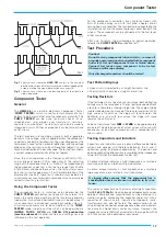
Fig. 1
shows a case where the
HOLD OFF
knob is in the minimum
position and various different waveforms are overlapped on the
screen, making the signal observation unsuccessful.
Fig. 2
shows a case where only the desired parts of the signal are
stably displayed.
Component Tester
General
The
HM303-6
has a built-in electronic Component Tester
(
COMP. TESTER
), which is used for instant display of a test
pattern to indicate whether or not components are faulty. The
COMP. TESTER
can be used for quick checks of se-
miconductors (e.g. diodes and transistors), resistors,
capacitors, and inductors. Certain tests can also be made to
integrated circuits. All these components can be tested in and
out of circuit.
The test principle is fascinatingly simple. A built-in generator
delivers a sine voltage, which is applied across the component
under test and a built-in fixed resistor. The sine voltage across the
test object is used for the horizontal deflection, and the voltage
drop across the resistor (i.e. current through test object) is used
for vertical deflection of the oscilloscope. The test pattern shows
a current-voltage characteristic of the test object.
Since this circuit operates with a frequency of 50Hz (±10%)
and a voltage of approx. 7Vrms (open circuit), the indicating
range of the component tester is limited. The impedance of
the component under test is limited to a range from 20
Ω
to
4.7k
Ω
. Below and above these values, the test pattern shows
only short-circuit or open-circuit. For the interpretation of the
displayed test pattern, these limits should always be borne in
mind. However, most electronic components can normally be
tested without any restriction.
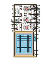
Using the Component Tester
The component tester is switched on by depressing the
COMP. TESTER
pushbutton (on) beneath the screen. This
makes the vertical preamplifier and the time base generator
inoperative. A shortened horizontal trace will be observed. It
is not necessary to disconnect scope input cables unless in-
circuit measurements are to be carried out. In the
COMP.
TESTER
mode, the only controls which can be operated are
INTENS
,
FOCUS
,
X-POS.
and
X-MAG. X10 pushbutton
(must be released).
All other controls and settings have no
influence on the test operation.
For the component connection, two simple test leads with
4mm Ø banana plugs, and with test prod, alligator clip or
sprung hook, are required. The test leads are connected to the
insulated socket and the adjacent ground socket beneath the
screen. The component can be connected to the test leads
either way round.
After use, to return the oscilloscope to normal operation,
release the
COMP. TESTER
pushbutton (off).
Test Procedure
Caution!
Do not test any component in live circuitry - remove all
grounds, power and signals connected to the component
under test. Set up Component Tester as stated above.
Connect test leads across component to be tested.
Observe oscilloscope display.
Only discharged capacitors should be tested!
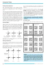
Test Pattern Displays
• Open circuit is indicated by a straight horizontal line.
• Short circuit is shown by a straight vertical line.
Testing Resistors
If the test object has a linear ohmic resistance, both deflecting
voltages are in the same phase. The test pattern expected from
a resistor is therefore a sloping straight line. The angle of slope
is determined by the resistance of the resistor under test. With
high values of resistance, the slope will tend towards the
horizontal axis, and with low values, the slope will move
towards the vertical axis.
Values of resistance from
20
Ω
Ω
Ω
Ω
Ω
to
4.7k
Ω
Ω
Ω
Ω
Ω
can be approximately
evaluated. The determination of actual values will come with
experience, or by direct comparison with a component of a
known value.
Testing Capacitors and Inductors
Capacitors and inductors cause a phase difference between
current and voltage, and therefore between the X and Y
deflection, giving an ellipse-shaped display. The position and
opening width of the ellipse will vary according to the impedance
value (at 50Hz) of the component under test.
A horizontal ellipse indicates a high impedance or a relatively
small capacitance or a relatively high inductance.
A vertical ellipse indicates a small impedance or a relatively
large capacitance or a relatively small inductance.
A sloping ellipse means that the component has a
considerable ohmic resistance in addition to its reac-
tance.
The values of capacitance of normal or electrolytic capacitors
from
0.1µF
to
1000µF
can be displayed and approximate values
obtained. More precise measurement can be obtained in a
smaller range by comparing the capacitor under test with a
capacitor of known value. Inductive components (coils,
transformers) can also be tested. The determination of the
value of inductance needs some experience, because inductors
have usually a higher ohmic series resistance. However, the
impedance value (at 50Hz) of an inductor in the range from 20
Ω
to 4.7k
Ω
can easily be obtained or compared.
Component Tester


