


14
Subject to change without notice
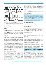
Phase difference measurement in DUAL mode
t
= horizontal spacing of the zero transitions in div.
T
= horizontal spacing for one period in div.
In the example illustrated,
t
= 3div. and
T
= 10div. The phase
difference in degrees is calculated from
or expressed in radians
Relatively small phase angles at not too high frequencies can be
measured more accurately in the X-Y mode with Lissajous figures.
Measurement of an amplitude modulation
The momentary amplitude u at time t of a HF-carrier voltage, which
is amplitude modulated without distortion by a sinusoidal AF
voltage, is in accordance with the equation
where
UT
= unmodulated carrier amplitude
Ω
Ω
Ω
Ω
Ω
=
2
πππππ
F
= angular carrier frequency
ω
ω
ω
ω
ω
=
2
πππππ
f
= modulation angular frequency
m
= modulation factor (i.a.
≤
1 100%).
The lower side frequency
F
-
f
and the upper side frequency
F+f
arise
because of the modulation apart from the carrier frequency
F
.
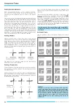
Figure 1.
Amplitude and frequency spectrum for AM display (m = 50%)
The display of the amplitude-modulated HF oscillation can be
evaluated with the oscilloscope provided the frequency spectrum
is inside the oscilloscope bandwidth. The time base is set so that
several cycles of the modulation frequency are visible. Strictly
speaking, triggering should be external with modulation frequency
(from the AF generator or a demodulator). However, internal
triggering is frequently possible with normal triggering (
AT/NM
button depressed) using a suitable
LEVEL
setting and possibly
also using the time variable adjustment.
Oscilloscope setting for a signal according to figure 2:
Depress no buttons.
Y: CH I; 20mV/div.; AC
.
TIME/DIV.:
0.2ms/div.
Triggering:
NM
(NORMAL);
with
LEVEL
-setting;
internal (or external) triggering.
Figure 2.
Amplitude modulated oscillation:
F
= 1 MHz;
f
= 1 kHz;
m
= 50 %;
UT
= 28.3 mV
rms
.
If the two values
a
and
b
are read from the screen, the
modulation factor is calculated from
where
a = U
T
(1+m)
and
b = U
T
(1-m).
The variable controls for amplitude and time can be set arbitrarily
in the modulation factor measurement. Their position does not
influence the result.
Triggering and time base
Time related amplitude changes on a measuring signal (AC
voltage) are displayable in Yt-mode. In this mode the signal
voltage deflects the beam in vertical direction while the time
base generator moves the beam from the left to the right of the
screen (time deflection).
Normally there are periodically repeating waveforms to be
displayed. Therefore the time base must repeat the time
deflection periodically too. To produce a stationary display, the
time base must only be triggered if the signal height and slope
condition coincide with the former time base start conditions.
A DC voltage signal can not be triggered as it is a constant signal
with no slope.
Triggering can be performed by the measuring signal itself
(internal triggering) or by an external supplied but synchronous
voltage (external triggering).
The trigger voltage should have a certain minimum amplitude.
This value is called the trigger threshold. It is measured with a
sine signal. When the trigger voltage is taken internally from the
test signal, the trigger threshold can be stated as vertical
display height in div., through which the time base generator
starts, the display is stable, and the trigger LED lights.
The internal trigger threshold of the
HM303-6
is given as £
0.5div. When the trigger voltage is externally supplied, it can be
measured in V
pp
at the
TRIG. EXT.
socket. Normally, the trigger
threshold may be exceeded up to a maximum factor of 20.
The
HM303-6
has two trigger modes, which are characterized
in the following.
Operating modes of the vertical amplifiers
Triggering and time base


