background image

26 


6.2 Installer settings 

- To open the installer settings, press 

  switch off the system, then press 

  and   

        at the same time for 10 seconds. 

- When menu is open, press 

  or 

  to change the value of the settings. 

- Press 

  to confirm the settings. 

- Press 

  to close the menu. 

Summary of Contents for HP200S1

Page 1: ...Pump Water Heater Installation and Service Manual Model Please read this manual carefully prior to your use of this water heater The appearance of the water heater given in this manual is for reference only ...

Page 2: ...principles 4 3 Technical parameters 5 4 Description of parts and components 6 5 Installation introduction 11 6 Operating and settings 24 7 Faults and protection 27 8 Faults and protection 29 9 The method of dismantling products 36 10 Repairs common tools 41 ...

Page 3: ... Children shall be closely supervised to make sure they stay away from this product 3 The method of installing safety valve please refer to Page 16 4 The water may drip from the discharge pipe of the pressure relief device and this pipe must be left open to the atmosphere 5 The water heater is to be drained according to the instructions specified on page 27 Safety instructions to be followed at an...

Page 4: ...ure of the refrigerant increases so does its temperature The heated refrigerant runs through a condenser coil within the storage tank transferring heat to the water stored there As the refrigerant delivers its heat to the water it cools and condenses and then passes through an expansion valve where the pressure is reduced and the cycle starts over ...

Page 5: ...5 3 Technical parameters ...

Page 6: ...6 4 Description of parts and components 4 1 Heat pump structure HP200 300S1 ...

Page 7: ...7 4 2 Exploded view 4 2 1 Exploded view tank unit ...

Page 8: ...Compressor The compressor is to effect a low temperature low pressure evaporator refrigerant vapor sucked and compressed into high temperature and pressure of the superheated vapor and then discharged to the condenser heat exchanger Inspiratory pipe Exhaust pipe Wiring box ...

Page 9: ...nt vapor is condensed into liquid during condensation the refrigerant vapor discharge heat the heat is absorbed by the heating medium 4 Thermal expansion valve The refrigerant passes through the thermal expansion valve the pressure from the condensing pressure is reduced to the evaporation pressure part of the refrigerant will evaporate into gas in the throttling process ...

Page 10: ...in the system thus affecting the life of the system components high pressure of the high voltage switch is 2 8MPa 7 Service valve Service valve is mainly used for filling refrigerant after removing the nuts it contains a valve needle sales staff can vacuum infusion refrigerant from here 8 Fan It forced air through the duct and then flows through a heat exchanger to improve heat transfer efficiency...

Page 11: ...in the position where exposed to gas vapours or dust Install the tank unit and external unit on a flat solid surface The surface can support the machine weight and the condensate water can be drained freely Noise due to operating and air flow do not bother neighbors Make sure there is sufficient space left for installation and maintenance There is no strong electromagnetic interference around that...

Page 12: ...all the internal unit in a dry frost free room Temperature of the ambient air or of the air taken in by the heat pump for optimum running from 10 to 35 C Discharge of condensate The condensate or water which is formed in the outdoor unit during heating operation must be eliminated freely or through the drain Fix the drain connection into the hole which is located on the bottom of the unit and conn...

Page 13: ...13 5 2 Installation dimensions mm ...

Page 14: ...to respond to the measures of the pipe unions d Flaring clamp ø nominal 1 4 and 3 8 equipped with a terminal receiving opening so that the projection of the copper tube can be adjusted from 0 to 0 5 mm in the working folder e Pipe cutter f Pipe reamer g Leak Detector for R134a a leak detector is used exclusively for HFC refrigerants It must have a high detection sensitivity 5 4 Preparing of the re...

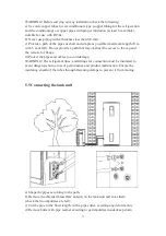
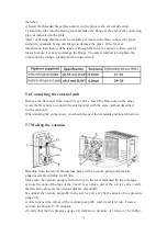
Page 15: ...access to the cap and the removal of flange d Protect the pipes and cables to avoid damage WARNING The refrigerant lines and fittings for connection must be insulated to avoid dangerous burns loss of performance and product malfunction Ensure the insulating sheath of the tubes through fastening clamps to prevent it from moving 5 5 Connecting the tank unit a Shape the pipes according to the path b ...

Page 16: ... valves Insert the flare nuts on the pipes screw the flare nuts to connect the external unit with the same method described for the tank unit When making the connections you should respect the standards and local directives 5 7 Making the vacuum Bleeding from the circuit should take place with a vacuum pump and pressure gauge assembly suitable for R134a Make sure the vacuum pump is full of oil up ...

Page 17: ...tack 1 2 UNF 20 threads per inch and corresponding seal Electronic scale for refrigerant charging with sensitivity 10g Connection pipes over 10 m need to increase the refrigerant 30g m During installation a Carry out the procedure of passage Āaāto the passage Āfā b Connect the manometer on the low pressure service valve and connect the refrigerant cylinder to the center tap of the the manometer Op...

Page 18: ... water inlet The inlet water temperature is suggested between 10 30eC Outdoor water pipeline and valves should be proper insulated In accordance with safety rules a safety valve 8 5bar 99eC G3 4M must be installed on the tank For France we recommend hydraulic safety units fitted with a membrane with the NF marking Integrate the safety valve in the cold water circuit Install the safety valve close ...

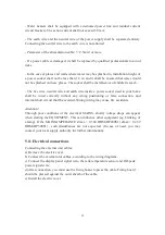
Page 19: ...er fittings in local market Valves with NF CE certification are recommended 5 10 Electrical connections precautions WARNING Only qualified professionals may carry out electrical connections always with the power off The earthing shall comply with local standards The heat pump water heater requires a single phase 16A HP200S1 20A HP300S1 supply requiring a licensed electrician for connecting ...

Page 20: ...in your home shall be wired correctly without any wrong positioning or false connection and internal short circuit shall be avoided Wrong wiring may cause fire accidents Attention Through poor conditions of the electrical MAINS shortly voltage drops can appear when starting the EQUIPMENT This can influence other equipment eg blinking of a lamp If the MAINS IMPEDANCE Zmax 0 304 OHM HP200S1 Zmax 0 2...

Page 21: ...21 ...

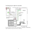
Page 22: ...22 5 12 Off peak power signal wire connection The heat pump water heater requires a single phase 16A HP200S1 20A HP300S1 supply requiring a licensed electrician for connecting ...

Page 23: ...23 5 13 Wiring diagram ...

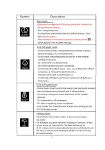
Page 24: ...24 6 Operation and functions Display 6 1 Description of the pictograms ...

Page 25: ...25 ...

Page 26: ...gs To open the installer settings press switch off the system then press and at the same time for 10 seconds When menu is open press or to change the value of the settings Press to confirm the settings Press to close the menu ...

Page 27: ...nance operations are important to guarantee optimum performance and extend the life of the equipment Checking the Safety valve Operate the safety valve at least one time per month to check if it is running correctly Otherwise check for blocking and replace the safety valve if necessary Checking the hydraulic circuit Check the watertightness of the water connections Cleaning the fan Check the clean...

Page 28: ...anliness An obstruction by dust may cause poor condensates flow or even a risk accumulation of water in the heat pump plastic base Checking the Magnesium rod The magnesium anode should be replaced in time avoid tank corrosion Checking magnesium anode once every 2 years In poor water areas need to shorten the time Drain the water tank to empty Cut off power supply and shut down water inlet valve th...

Page 29: ...29 8 Faults and protection 8 1 Fault type ...

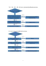
Page 30: ...30 8 2 Fault code identification method ...

Page 31: ...31 ...

Page 32: ...32 ...

Page 33: ...33 ...

Page 34: ...uring the resistance value of the compressor of the same but is switched to the small resistance of the interface unit Multimeter set to Ohms according to the picture of the method of measuring the resistance of the temperature sensor According to the resistance table the lower the temperature the smaller the resistance ...

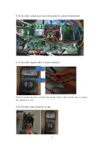
Page 35: ...line is through the current transformer 8 5 Check the signal cable is short circuited Press the yellow button to switch to the picture when a short circuit there is a beep the resistance is zero 8 6 Check the tank heater for leaks ...

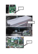
Page 36: ...ot leak show resistance 8 7 Check that the power cord L N lines are in the same order into the leakage protection coil 9 The method of dismantling products Make sure the power cord is disconnected 9 1 Remove the Display leakage protection coil Use a screwdriver to remove the two screws Use a screwdriver to remove the two screws ...

Page 37: ...37 9 2 Remove the Control panel Use a screwdriver to remove the screws Remove it Remove it ...

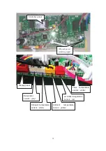
Page 38: ...t temperature sensor yellow Exhaust temperature sensor white air intake temperature sensor red Evaporator sensor grey Tank temperature sensor white Display panel Off peak power switching signal Controller panel ...

Page 39: ...lve exhaust pressure when no water flows out of timeˈturn off all the valves Remove the ķ top cover After remove the ĸ nuts of magnesium flange according to the consumption of magnesium rod determine whether you need to replace nuts of magnesium flange magnesium rod 1 remove the screw 2 remove the fan 3 remove the motor ...

Page 40: ... Electrical cover 9 6 2 Remove the internal wiring and electric heater Temperature tube up Temperature tube down First insert the temperature sensor and then insert the thermostat temperature sensor Temperature sensor must be inserted into the bottom of the tube magnesium flange Use a screwdriver to remove the 2 screws After the tank has been emptied with a socket wrench to remove the electric hea...

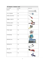
Page 41: ... Illustration Spanner 2pc Hexagon Spanner 1pc Flathead screwdriver 1pc Phillips screwdriver 1pc Needle nose pliers 1pc Measuring tape 1pc Pressure gauge 1pc Vacuum pump 1pc Electronic scale 1pc Bending device 1pc Pipe cutter 1pc Flaring device 1pc ...

Reviews: