19
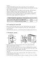
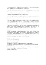
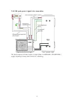
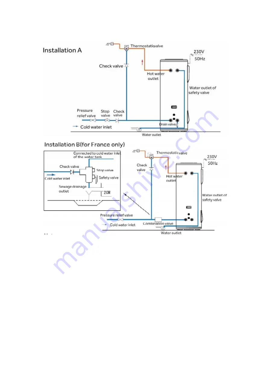
Pipeline installation diagram
- Pressure relief valve, thermostatic valve, stop valve, check valve, T&P valve and
French combination valve are not included in the accessories, please select proper
fittings in local market;
- Valves with NF/CE certification are recommended
5.10 Electrical connections precautions
WARNING
- Only qualified professionals may carry out electrical connections, always with the
power off.
- The earthing shall comply with local standards.
-The heat pump water heater requires a single phase 16A(HP200S1)/20A(HP300S1)
supply requiring a licensed electrician for connecting.
Summary of Contents for HP200S1
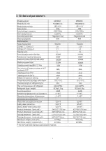
Page 5: ...5 3 Technical parameters ...
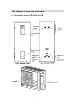
Page 6: ...6 4 Description of parts and components 4 1 Heat pump structure HP200 300S1 ...
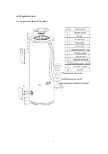
Page 7: ...7 4 2 Exploded view 4 2 1 Exploded view tank unit ...
Page 13: ...13 5 2 Installation dimensions mm ...
Page 21: ...21 ...
Page 23: ...23 5 13 Wiring diagram ...
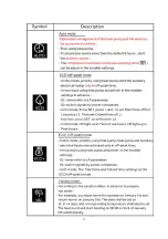
Page 24: ...24 6 Operation and functions Display 6 1 Description of the pictograms ...
Page 25: ...25 ...
Page 29: ...29 8 Faults and protection 8 1 Fault type ...
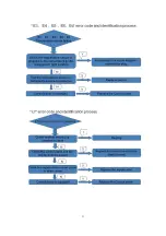
Page 30: ...30 8 2 Fault code identification method ...
Page 31: ...31 ...
Page 32: ...32 ...
Page 33: ...33 ...
Page 37: ...37 9 2 Remove the Control panel Use a screwdriver to remove the screws Remove it Remove it ...

