16
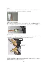
the tube);
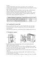
e) Insert the threaded brass flare nuts(A) on the pipes in the correct direction;
f ) Insert the tube into the flaring tool and make the flange at the end of the connecting
pipe, as indicated in the table.
After confirming that there are no wrinkles or tears on the flare, connect the pipes
using two spanners, being careful not to damage the pipes. If the force is
insufficient, then there will be leaks. Although the force is excessive, there may be
losses because it is easy to damage the flange. The safest method is to tighten the
connection by using a spanner and a torque wrench.
15
5.6 Connecting the external unit
Remove the flare nuts from 2 and 3 way valves, Insert the flare nuts on the pipes,
screw the flare nuts to connect the external unit with the same method described
for the tank unit.
When making the connections, you should respect the standards and local directives.
5.7 Making the vacuum
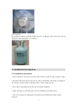
Bleeding from the circuit should take place with a vacuum pump and pressure
gauge assembly suitable for R134a.
Make sure the vacuum pump is full of oil up to the level indicated by the oil gauge.
a) loose the caps of the taps of the 2 and 3 way valves, and of the service valve; verify
that the two valves on the outdoor unit are closed (D);
b) connect the vacuum pump (B) to the service valve (C) by the attack of low pressure
gauge (A);
c) After opened the valves of the vacuum pump (B), start it and let it run. Create a
vacuum for about 20 / 25 minutes;
d) verify that the low pressure gauge (A) indicates a pressure of 1 bar-(or -76 cm Hg);
Summary of Contents for HP200S1
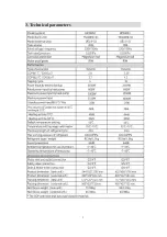
Page 5: ...5 3 Technical parameters ...
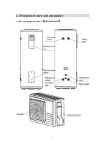
Page 6: ...6 4 Description of parts and components 4 1 Heat pump structure HP200 300S1 ...
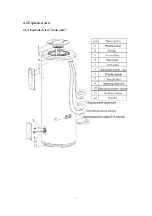
Page 7: ...7 4 2 Exploded view 4 2 1 Exploded view tank unit ...
Page 13: ...13 5 2 Installation dimensions mm ...
Page 21: ...21 ...
Page 23: ...23 5 13 Wiring diagram ...
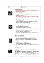
Page 24: ...24 6 Operation and functions Display 6 1 Description of the pictograms ...
Page 25: ...25 ...
Page 29: ...29 8 Faults and protection 8 1 Fault type ...
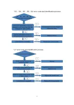
Page 30: ...30 8 2 Fault code identification method ...
Page 31: ...31 ...
Page 32: ...32 ...
Page 33: ...33 ...
Page 37: ...37 9 2 Remove the Control panel Use a screwdriver to remove the screws Remove it Remove it ...

