20
- Water heaters shall be equipped with a dedicated power line and residual current
circuit breakers. The action current shall not exceed 30 mA;
- The earth wire and the neutral wire of the power supply shall be separated entirely.
Connecting the neutral wire to the earth wire is not allowed.
- Parameter of the alimentation cable: 3×2.5mm² or more.
- If a power cable is damaged, it shall be replaced by qualified professionals to avoid
risks.
- In the case of places and walls where water may be splashed to, installation height of
a power socket shall not be less than 1.8 m, and it shall be ensured that water would
not be splashed on these places. The socket shall be installed out of children’s reach.
- The live wire, neutral wire and earth wire inside a power socket used in your home
shall be wired correctly without any wrong positioning or false connection, and
internal short circuit shall be avoided. Wrong wiring may cause fire accidents.
Attention!
Through poor conditions of the electrical MAINS, shortly voltage drops can appear
when starting the EQUIPMENT. This can influence other equipment (eg. blinking of
a lamp). If the MAINS-IMPEDANCE Zmax < 0.304 OHM(HP200S1) Zmax < 0.289
OHM(HP300S1) , such disturbances are not expected. (In case of need, you may
contact your local supply authority for further information).
5.11 Electrical connections
Connecting the external unit cables:
a) Remove the electric cover.
b) Connect the external unit cables, according to the wiring diagrams .
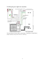
c) Connect the display panel signal wire, the tank temperature sensor and Off-peak
power signal wire .
d) After connection, you must use the fixing board to press the cable. Fixing board
should be pressed against the outer sheath of the cable.
e) Install the electric cover.
Summary of Contents for HP200S1
Page 5: ...5 3 Technical parameters ...
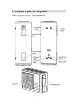
Page 6: ...6 4 Description of parts and components 4 1 Heat pump structure HP200 300S1 ...
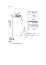
Page 7: ...7 4 2 Exploded view 4 2 1 Exploded view tank unit ...
Page 13: ...13 5 2 Installation dimensions mm ...
Page 21: ...21 ...
Page 23: ...23 5 13 Wiring diagram ...
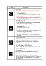
Page 24: ...24 6 Operation and functions Display 6 1 Description of the pictograms ...
Page 25: ...25 ...
Page 29: ...29 8 Faults and protection 8 1 Fault type ...
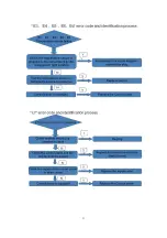
Page 30: ...30 8 2 Fault code identification method ...
Page 31: ...31 ...
Page 32: ...32 ...
Page 33: ...33 ...
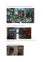
Page 37: ...37 9 2 Remove the Control panel Use a screwdriver to remove the screws Remove it Remove it ...

