SECTION 7 –
SPRAY SYSTEMS
7-43
7. Remove operator-supplied connection
from the Rinse Tank Fill Port.
8. Reinstall the fill port cap.
9. Raise the Front Fill Assembly to the
stored position, ensuring it “clicks” into
locked position.
Side Fill
-If Equipped
NOTE: Engage parking brake before
operating the side fill.
Filling the Solution Tank
(Inductor Operation)
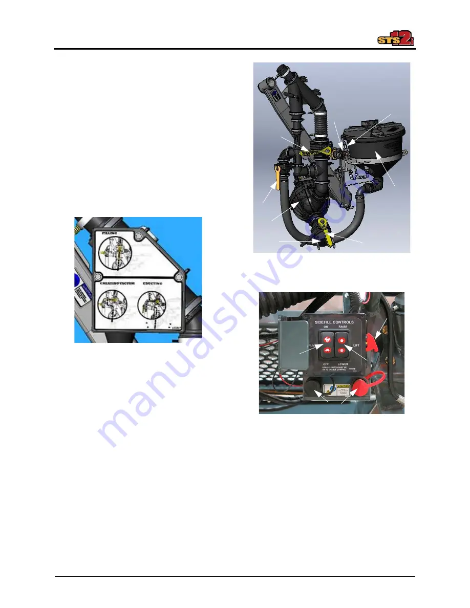
Inductor Assembly Components
•
(A) - Side Fill Valve
•
(B) - Rinse Supply Valve
•
(C) - Chemical Inductor Valve
•
(D) - Transfer Pump
•
(E) - Swirl Valve
•
(F) - Chemical Inductor Tank
•
(G) - Fill Port
•
(H) - Fill Valve
•
(I) - Pump Speed Switch
•
(J) - Raise/Lower Switch
•
(K) - Pump Activation Lever
•
(L) - Power Ports
NOTE: Two power ports (located beneath
the Side Fill Control Panel) are
provided for chemical pump
connection.
Sidefill Operation Label
(Located on sidefill)
-Typical View
Inductor Assembly
-Typical View
A
B
C
D
F
G
H
E
Side Fill Control Panel
-Typical View
L
K
I
J
Summary of Contents for STS12i Combo
Page 276: ......


