


17
ROSSI
GEARMOTORS
UT.D 045 rev. 5
running. For the next filling use a 60
m oil filter.
Replace the seal rings in case of dismounting or of periodical check
of gear reducer; in this case, the new ring must be positioned so that
the new ring does not work on the same sliding race of previous
ring.
When dismounting the cap (whenever gear reducers are provided
with), reset the sealing with adhesive on cleaned and degreased
mating surfaces.
9.2 - Coil
In case of long non-running periods at ambient temperatures lower
than 0 °C, the coil should be emptied out using compressed air to
blast out all the coolant, so as to avoid freezing-up which would
cause the coil to break.
9.3 - Seal rings
It is always recommended that the seal rings are replaced with new
ones when they are removed or during periodic checks of gear redu-
cer; in this case, the new ring should be generously greased and
positioned so that the seal line does not work on the same point of
sliding contact as the previous ring.
Oil seals must be protected against heat radiation, also during the
shrink fitting of parts, if applicable.
9.4 - Motor replacement
Since gearmotors are realised with
standardised
motor, motor
re placement – in case of failure – is extremely easy. Simply observe
the following instructions:
– be sure that the mating surfaces are machined under accuracy
rating (UNEL 13501-69; DIN 42955);
– clean surfaces to be fitted thoroughly;
– check and, if necessary, lower the parallel key so as to leave a
clearance of 0,1
0,2 mm between its top and the bottom of the
keyway of the hole. If shaft keyway is without shoulder, lock the
key with a pin.
For worm gearmotors MR V, parallel shaft gearmotrs MR 2I and
MR 3I 140 ... 360, right angle shaft gearmotors MR CI, C2I
(motor
shaft end keyed directly into the worm, the cylindrical or bevel pnion
shaft, respectively);
– check that the fit-tolerance (push-fit) between hole and shaft end
is G7/j6 for D
28 mm, F7/k6 for D
38 mm;
– lubricate surfaces to be fitted against fretting corrosion.
For parallel shaft gearmotors
(2I, 3I)
with motor size 200 ... 315
and gearmotors MR V, MR 2I and MR CI with non-standard
design «Square flange for servomotors», proceed as follows for
disassembling:
– align the key through hole with the tightening screw of the hub clamp;
– loosen the tightening screw and consequently the hub clamp;
– disassemble the motor.
For worm gearmotors MR IV, parallel shaft gearmotors MR 3I
40 ... 125 and MR 4I, right angle shafts gearmotors MR ICI and
MR C3I, coaxial gearmotors
(cylindrical pinion keyed on to the
motor shaft end);
– check that the fit-tolerance (standard locking) between hole and
shaft end is K6/j6 for D
28 mm, and J6/k6 for D
38 mm; key
length should be at least 0,9 pinion width;
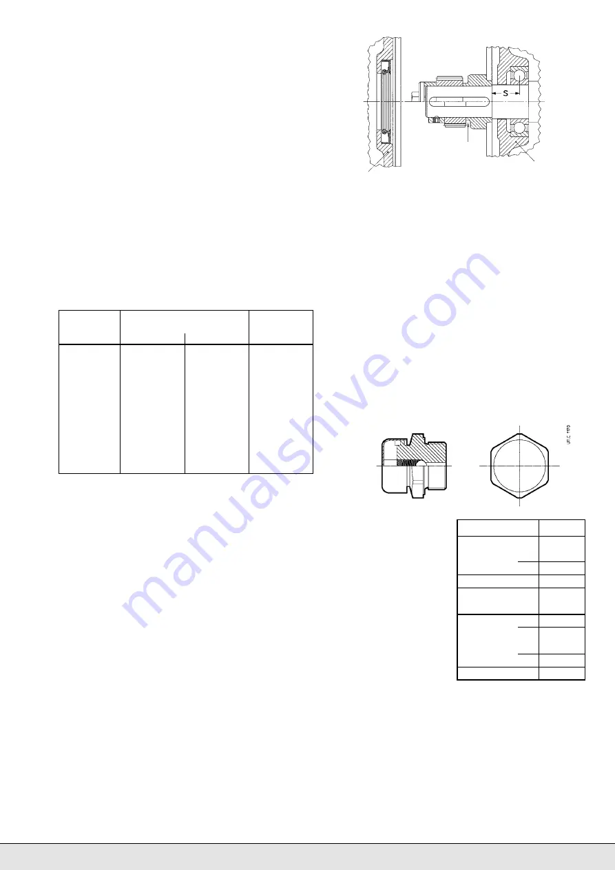
– make sure that the motors have bearing location and overhang
(distance S) as shown in the table;
– locate the spacer (with adhesive, check that between keyway
and motor shaft shoulder there is a grounded cylindrical part of at
least 1,5 mm) and pinion on the motor (pinion pre-heated to +80
+100 °C) locking the entire assembly by means of a bolt to the
butt-end or hub clamp;
– grease the pinion teeth, the sealing ring rotary seating and the ring
itself, and assemble carefully.
10 - Sound levels
Most of the ROSSI MOTORI-
DUTTORI product range is cha-
racterised
by
sound pressure
levels
L
¯
pA
(mean value of mea-
surement, assuming nominal
load and input speed
n
1
=
1 400 min
-1
, at 1 m from exter-
nal profile of gear reducer stan-
ding in free field on a reflecting
surface, according to draft pro-
posal ISO/CD 8579)
lower or
equal to 85 dB(A).
The table indicates the pro ducts
which
can exceed
a.m. thre-
shold. For further information
about sound levels of every sin-
gle
product
see
ROSSI
MO TORIDUTTORI
technical
catalogues.
Motor
Min dynamic load capacity
Max dimension
size
daN
‘S’ mm
Front
Rear
63
450
335
16
71
630
475
18
80
900
670
20
90
1 320
1 000
22,5
100
2 000
1 500
25
112
2 500
1 900
28
132
3 550
2 650
33,5
160
4 750
3 350
37,5
180
6 300
4 500
40
200
8 000
5 600
45
225
10 000
7 100
47,5
250
12 500
9 000
53
280
16 000
11 200
56
Machine/Train of gears
i
N
Size
Parallel shaft
R I
3,15
160
4
200
R 2I
all
320
R 3I
all
400
R 4I
160
500
200
630
Right angle shaft R CI
all
320
R C2I
63
400
71
500
R C3I
all
630
Right angle shaft R C
1
250
gear reducer
motor
groove for pulling
pinion
U
T.C
725
9.5 - Bearings
Since there are many different types of bearings in a gear reducer
(roller, tapered roller, straight roller, etc.) and each bearing works with
different loads and speeds depending on the input speed, the nature
of the load of the driven machine, the transmission ratio, etc., and
with different lubricants (oil bath, oil splash, grease, oil circulation,
etc.), it is not possible to define any periodical maintenance and
replacement of bearings in advance.
If a precautionally maintenance is required,
undertake periodical
checks to verify noise level and vibration with the help of appro-
piate diagniostic equipment and instruments
. If the measured
values worsen even slightly it is necessary to stop gear reducer or
gear motor and after having inspected inside the unit replace the
bearings which are subject to breakdown.
9.6 - Metal filler plug with filter and valve
When the gear reducer or gearmotor (size
100) is equipped with
metal filler plug with filter and valve (see fig. here following), in order
to clean it, it is necessary to unscrew it from the gear reducer (pre-
venting any debris or other foreign items from entering the reducer,
disassemble the cover, wash it with solvent, dry with compressed
air and reassemble it). This operation is to be made according to
environment conditions.


