background image


90 

Item Description 

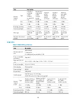
Maximum transmission 
distance 

0.55 km 
(0.34 miles) 

10 km (6.21 
miles) 

40 km (24.86 
miles) 

40 km (24.86 
miles) 

70 km (43.50 
miles) 


Lightning protector for a network port (optional) 

If part of the network cable of a network port must be routed outdoors, connect a lightning protector to 
the cable before you plug the cable into the port. 

The specifications for the lightning protector for a network port are as follows: 1000 M port protective 
unit–single port, maximum discharge current (8/20

μ

s waveform): 3 kA, output voltage: core-core < 15 

V, core-ground < 350 V.  

For how to install a lightning protector for a network port, see "

Installing a lightning protector for a 

network port

." 

Power strip with lightning protection (optional) 

If part of the AC power line is routed outdoors, use a power strip with lightning protection to connect the 
AC power cord of the firewall to the AC power line to protect the firewall from being damaged by 
lightning strikes.  

The specifications for the power strip with lightning protection are as follows: Maximum discharge current: 
6500 A, protection voltage: 220 VAC to 500 VAC.  

For how to connect the AC power supply to a power strip with lightning protection, see "

Connecting the 

AC power supply to a power strip with lightning protection

." 


Summary of Contents for SecPath F5000-A5

Page 1: ...H3C SecPath F5000 A5 Firewall Installation Guide Hangzhou H3C Technologies Co Ltd http www h3c com Document version 6PW109 20141225...

Page 2: ...d All other trademarks that may be mentioned in this manual are the property of their respective owners Notice The information in this document is subject to change without notice Every effort has bee...

Page 3: ...s section describes the conventions used in this documentation set Command conventions Convention Description Boldface Bold text represents commands and keywords that you enter literally as shown Ital...

Page 4: ...an result in data loss data corruption or damage to hardware or software IMPORTANT An alert that calls attention to essential information NOTE An alert that contains additional or supplementary inform...

Page 5: ...os and provide configuration examples and instructions Operations and maintenance Release notes Provide information about the product release including the version history hardware and software compat...

Page 6: ...Documentation feedback You can e mail your comments about product documentation to info h3c com We appreciate your comments...

Page 7: ...before installation 8 Installing the firewall 10 Confirming installation preparations 10 Installing the firewall in a 19 inch rack 11 Installing cage nuts to the rack 11 Attaching the mounting bracke...

Page 8: ...43 Performing basic configurations at the CLI 43 Performing basic configurations in the Web interface 44 Replacement procedures 51 Precautions 51 Installing and removing a filler panel 51 Removing a f...

Page 9: ...on system failures 74 No display on the configuration terminal 75 Garbled characters on the configuration terminal 75 Console port failure 75 Password loss 76 Cooling system failures 76 Software upgra...

Page 10: ...NSQ1GT8P40 94 Power module LEDs 95 Fan tray LEDs 96 Appendix C Arranging slots and numbering interfaces 97 Arranging slots 97 Numbering interfaces 97 Examples 98 Appendix D Cables 99 Ethernet twisted...

Page 11: ...nd flat and anti slip measures are in place Keep the chassis and installation tools away from walk areas Make sure the installation site is correctly grounded and lightning protection and ESD preventi...

Page 12: ...e chassis requires at least two persons Lift and put down the chassis slowly and never move suddenly Hold the handles on the chassis If the firewall needs to be moved over a long distance remove all f...

Page 13: ...operating and storage 40 C to 70 C 40 F to 158 F Operating 10 to 95 noncondensing Nonoperating and storage 5 to 95 noncondensing Cleanness Dust buildup on the chassis may result in electrostatic adsor...

Page 14: ...esistance reading should be in the range of 1 to 10 megohm Mohm between human body and the ground The F5000 A5 does not provide any ESD wrist strap Prepare it yourself To prevent electrostatic dischar...

Page 15: ...service card Make sure the rack is correctly grounded before you wear an ESD wrist strap To attach the ESD wrist strap 1 Wear the wrist strap on your wrist 2 Lock the wrist strap tight around your wr...

Page 16: ...he firewall from lightning better do as follows Make sure the chassis is correctly grounded Make sure the grounding terminal of the AC power receptacle is correctly grounded Install a lightning protec...

Page 17: ...wdriver Phillips screwdriver Needle nose pliers Wire stripping pliers Diagonal pliers RJ 45 crimping pliers Marker Multimeter Network cable tester Hot air blowing gun Accessories Console cable supplie...

Page 18: ...an ESD wrist strap and uniform when touching a circuit board Place the removed MPU service card and CF card on an antistatic workbench with the face upward or put it into an antistatic bag Touch only...

Page 19: ...in a closed cabinet make sure the cabinet is equipped with a good ventilation system The rack is sturdy enough to support the weight of the firewall and installation accessories The size of the rack...

Page 20: ...he firewall IMPORTANT Keep the packages of the firewall and the components for future use Figure 3 F5000 A5 firewall installation flow Confirming installation preparations Before you install the firew...

Page 21: ...e firewall is ready for installation and has been carried to a place near the installation site and convenient for moving Installing the firewall in a 19 inch rack To install the F5000 A5 in a 19 inch...

Page 22: ...Mounting bracket Figure 6 Mounting bracket 1 Left mounting bracket 2 Right mounting bracket Attaching the cable management bracket As shown in Figure 7 before you attach a mounting bracket to the chas...

Page 23: ...rackets to the chassis Before you mount the firewall to the rack attach the front mounting brackets to the two sides of the chassis To attach the front mounting brackets to the firewall align the scre...

Page 24: ...king sure there is enough clearance between the firewall and rack posts for installing the mounting brackets 2 Attach the firewall horizontally by fastening the mounting brackets to the rack with appr...

Page 25: ...ased an air filter install the air filter before mounting the firewall to the rack For how to install an air filter see Installing an air filter Grounding the firewall WARNING Correctly connecting the...

Page 26: ...n sheath by using a wire stripper and insert the bare metal part through the black insulation covering into the end of the ring terminal 3 Secure the metal part of the cable to the ring terminal with...

Page 27: ...firewall to connect to the grounding strip in the equipment room as long as possible Installing an MPU 1 Locate the slot to install the MPU 2 Remove the filler panel from slot 0 For how to remove a fi...

Page 28: ...Fasten the captive screws with a Phillips screwdriver Figure 13 Fastening the captive screws 5 The RUN LED green flashes fast at 8 Hz It flashes slowly at 1 Hz after the MPU application is loaded This...

Page 29: ...2 Push the CF card eject button all the way into the slot and make sure the button does not project from the panel 3 Insert the CF card into the slot following the direction shown in Figure 14 and mak...

Page 30: ...on the backplane and then push the ejector levers inward to lock the interface module in position If an interface module cannot be installed smoothly remove the upper and lower filler panels on the sl...

Page 31: ...ting correctly For more information about interface module LEDs see Interface module LEDs If all of the slots 1 through 4 are installed with an interface module the RUN LEDs on them light in the order...

Page 32: ...rewdriver to fasten the captive screws on the fan tray Figure 18 Fastening the captive screws on the fan tray 4 Power on the firewall and examine the status LED on the front panel On means the fan tra...

Page 33: ...dule as an example 1 Locate the slot to install the power module Use even pressure to gently push the power module slowly along the slide rails into the slot Figure 19 Installing the power module 2 Fa...

Page 34: ...ration terminal Figure 20 Connecting the management Ethernet port 1 Management Ethernet port MANAGEMENT 2 RJ 45 connector 3 Ethernet cable Connecting the HA port The high availability HA port a 10Base...

Page 35: ...port LED status For more information about the LED status see Appendix B LEDs After you connect the firewall to the network execute the ping or tracert command to test network connectivity For more i...

Page 36: ...ne fiber cable into the Rx port of the firewall and the LC connector at the other end into the Tx port of the peer device Plug the LC connector at one end of another fiber cable into the Tx port of th...

Page 37: ...eptacle on the firewall and the other end to the AC power source Figure 23 Connecting an AC power cord to the firewall Connecting a DC power cord WARNING Identify the label on the DC power cord when c...

Page 38: ...Where I Current in amperes L Length of the power cord in meters V Voltage drop on the power cord from the power distribution frame PDF to the firewall usually 3 2 V S Cross section area of the power c...

Page 39: ...ensure normal operation of the firewall verify the following items before you power on the firewall There is enough space for heat dissipation around the firewall The grounding cable is securely conne...

Page 40: ...filter 1 Face the left side of the chassis 2 Install the upper slide rail for the air filter to the upper side of the chassis 3 Fasten the screws on the slide rail with a Phillips screwdriver 4 Repeat...

Page 41: ...ver Figure 28 Fastening the captive screws Installing a lightning protector for a network port The lightning protector for a network port is only applicable to a copper Ethernet port If part of the ne...

Page 42: ...ick the lightning protector onto the firewall chassis and make sure it is as close to the grounding screw of the firewall as possible 2 Measure the distance between the protector and the grounding scr...

Page 43: ...nnect the IN end to the outdoor network cable and the OUT end to the network port on the firewall The port lightning protector is not well grounded After the connection use the multimeter to confirm t...

Page 44: ...et for wrong connections If the zero wire left and the live wire right are correctly connected check for missing grounding connection Figure 30 Power strip with lightning protection 1 Operating LED gr...

Page 45: ...gh the console port you must have a console cable and a terminal for example a PC The terminal can be any character terminal with an RS 232 port or a PC Typically a PC running a terminal emulation pro...

Page 46: ...rial ports on PCs do not support hot swapping If the firewall has been powered on always connect the console cable to the PC before connecting it to the firewall and when you disconnect the cable firs...

Page 47: ...re 32 Creating a HyperTerminal connection 3 Select the serial port used to connect to the firewall and click OK Figure 33 Selecting the serial port 4 Configure serial port properties as described in T...

Page 48: ...e Bits per second 9600 bps the default Data bits 8 Parity None Stop bits 1 Flow control None NOTE If you are using SecureCRT set the flow control property to Xon Xoff to ensure correct display To rest...

Page 49: ...39 Figure 35 HyperTerminal window 6 Select File Properties and then click the Settings tab Figure 36 Selecting the emulation type 7 Select VT100 or Auto detect for Emulation and click OK...

Page 50: ...how that the firewall is operating correctly For more information about the LED behaviors see Appendix B LEDs 2 The cooling system is working and you can hear fan rotating noise and feel air being blo...

Page 51: ...the extended Boot menu The boot information depends on the software version Logging in to the CLI by using Telnet This section provides only a simplified procedure for logging in to the CLI by using...

Page 52: ...he network segment 192 168 0 0 24 except for 192 168 0 1 for example 192 168 0 2 3 Launch a Web browser on the PC and enter 192 168 0 1 in the address bar The Web login page appears Figure 37 Web logi...

Page 53: ...s for performing basic configurations on the firewall For how to configure protocols and features on the firewall see the firewall configuration guides The syntax of commands and the Web interface var...

Page 54: ...any zone 8 Return to the upper level view quit N A 9 Save the running configuration save safely N A 10 Display the running configuration display current configuration N A Performing basic configuratio...

Page 55: ...ify whether to change the login password To change the password enter the new password and confirm it For versions prior to F3210 the default username and password are both h3c For F3210 and later ver...

Page 56: ...t service on the firewall By default the Telnet service is disabled HTTP Specify whether to enable the HTTP service on the firewall To enable the HTTP service on the firewall select the Enable option...

Page 57: ...Make sure no other services are using the specified service port number HTTPS uses the PKI domain default by default If the PKI domain does not exist you will see an error message at the end of the w...

Page 58: ...ng the IP address of the interface you are using disconnects you from the firewall IP Address Configure an IP address and a mask for the interface These two fields are available only when the value of...

Page 59: ...accesses the internal server the NAT function translates the destination address of the request packets into the private IP address of the internal server Accordingly when the internal server replies...

Page 60: ...uration click Back to go back to the previous page 3 To save the current configuration to the startup configuration file cfg or xml file for the next device boot when you submit the configurations sel...

Page 61: ...Hold a PCB by its edges Do not touch any electronic components Put the removed FRUs on an antistatic workbench with the PCB side facing upward or place them in antistatic bags Installing and removing...

Page 62: ...ide view 3 Rear oblique view 4 EMI gasket Removing a filler panel This section takes the filler panel for an interface module slot as an example To remove a filler panel 1 Face the front panel of the...

Page 63: ...event dust from entering the firewall chassis and make sure of good ventilation in the firewall Installing a filler panel This section takes the filler panel for an interface module slot as an example...

Page 64: ...module slot Replacing an MPU IMPORTANT MPUs are not hot swappable Before you remove MPUs power off the firewall To replace an MPU 1 Face the front panel of the firewall 2 Loosen the captive screws wit...

Page 65: ...he captive screws 3 Pull the two ejector levers at both ends of the MPU outward to release the MPU and then gently pull the MPU out along the slide rails Put the removed MPU in an antistatic bag Figur...

Page 66: ...e Interface modules power off the firewall To replace an interface module 1 Face the front panel of the firewall 2 Loosen the captive screws on the interface module with a Phillips screwdriver until a...

Page 67: ...CAUTION To avoid hardware damage do not remove the CF card when the firewall is booting or the LED is flashing To replace a CF Card 1 Identify whether the CF card LED is flashing If yes the system is...

Page 68: ...ing a CF card Replacing a transceiver module WARNING When you remove a transceiver module do not touch the golden finger on the module Do not stare at the fibers to avoid hurting your eyes Make sure t...

Page 69: ...dures see Connecting a fiber port Figure 53 Replacing a transceiver module Replacing a power module The F5000 A5 firewall supports AC and DC power modules The following describes how to remove an AC p...

Page 70: ...from entering the chassis Replacing a fan tray CAUTION Keep your hands away from the spinning fan blades when removing the fan tray Do not keep the firewall working without a fan tray for a long time...

Page 71: ...ptive screws 3 Gently pull the fan tray out along the slide rails Put the removed fan tray in an antistatic bag Figure 56 Pulling out the fan tray 4 Install a new fan tray For the installation procedu...

Page 72: ...ghts reserved H3C SecPath F5000 A5 uptime is 0 week 0 day 0 hour 57 minutes CPU type XXXX 3584M bytes DDR2 SDRAM Memory 4M bytes Flash Memory 247M bytes CF0 Card MPUA PCB Version Ver B SWBA PCB Versio...

Page 73: ...iag aa diag Diagnostic information is outputting to cfa0 aa diag Please wait Save successfully To view the content of file aa diag execute the more aa diag command in user view in combination of the P...

Page 74: ...ive information including name of the card card serial number MAC address and vendor name Use the display device manuinfo command to display the electronic label data for the cards Sysname display dev...

Page 75: ...e every five minutes This field displays the average CPU usage rate in the last five minutes Displaying memory usage statistics Use the display memory command to display memory usage statistics Sysnam...

Page 76: ...Table 13 Command output Field Description Fan 1 Number of fan State Fan status which can be Normal The fan is operating correctly Absent The fan is not present Fault The fan has failed Displaying powe...

Page 77: ...ace Loopback is not set Media type is not sure Port hardware type is No connector Unknown speed mode unknown duplex mode Link speed type is autonegotiation link duplex type is autonegotiation If the c...

Page 78: ...lay key parameters of the transceiver module in a specified interface display transceiver interface interface type interface number Available for all transceiver modules Diagnosing transceiver modules...

Page 79: ...ule a reboot to occur at a specific time and date or after a delay Power off and then re power on the firewall This method also known as hardware reboot or cold reboot might cause data loss and is the...

Page 80: ...sk Command Remarks Enable the scheduled reboot function and specify a reboot waiting time schedule reboot delay hh mm mm Optional The scheduled reboot function is disabled by default Available in user...

Page 81: ...R LED of the power module indicates that the firewall is powered on normally If the cause cannot be located in the previous steps and the problem persists contact your local sales agent Symptom 2 Symp...

Page 82: ...s that the service module is powered off or faulty Solution 1 Verify that the firewall is powered on 2 Verify that the service module is plugged in a right slot slot 1 through slot 4 3 If the service...

Page 83: ...r source is turned on 4 Verify that the power cord is in good condition If the cause cannot be located in the previous steps and the problem persists contact your local sales agent Symptom 2 Symptom T...

Page 84: ...appears on the configuration terminal Jul 5 14 59 03 878 2007 H3C DRVMSG 3 FanPlugIn Fan 1 Plug In Jul 5 14 59 03 879 2007 H3C DRVMSG 3 FanErr Fan 1 Error Jul 5 14 59 03 998 2007 H3C DEV 1 FAN STATE...

Page 85: ...ulation to VT100 The console cable is broken If the cause cannot be located in the previous steps and the problem persists contact your local sales agent Garbled characters on the configuration termin...

Page 86: ...the temperature inside the firewall exceeds 75 C 167 F the following information appears on the configuration terminal May 14 21 37 35 271 2007 H3C DRVMSG 3 Temp2High Environment temperature too high...

Page 87: ...and to examine whether the temperature inside the firewall is rising When the fans are running normally and the working environment is well ventilated if the temperature inside the firewall exceeds 90...

Page 88: ...ough FTP Symptom Start the firewall and upgrade the software through FTP The following problems might occur Symptom 1 The CF card has no enough space 227 Entering Passive Mode 192 168 1 10 10 204 150...

Page 89: ...pplication file does not exist cfa0 main bin Starting to get the backup application file cfa0 backup bin The backup application file does not exist cfa0 backup bin Starting to get the secure applicati...

Page 90: ...the chassis weight Figure 57 Front view 1 MPU slot Slot 0 2 Fan tray slot 3 Chassis handle 4 Weight support warning label Max weight of 50 kg 110 23 lb 5 Power module slot 1 PWR1 6 PoE power module f...

Page 91: ...eight of 50 kg 110 23 lb 8 Grounding screw and sign 9 Air vents Main processing unit The F5000 A5 firewall supports only one MPU which must be installed in slot 0 Figure 59 MPU panel view 1 10 100 100...

Page 92: ...0 100 1000BASE T copper port and one 1000BASE X fiber port When one port in a pair is activated the other port automatically shuts down Figure 60 NSQ1GT8C40 panel view 1 8 copper Ethernet ports 2 4 co...

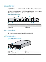
Page 93: ...ort in a pair is activated the other port automatically shuts down Figure 62 NSQ1GT8P40 panel view 1 8 Ethernet fiber ports SFP0 to SFP7 2 4 combo interfaces 3 Fiber port in a combo interface 4 Copper...

Page 94: ...C power module 1 DC input terminal block 2 Power LED 3 Power module handle 4 Power switch 5 Captive screw Fan tray Figure 65 F5000 A5 fan tray 1 Running status LED RUN 2 Alarm LED ALM 3 Fan tray handl...

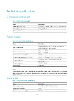
Page 95: ...wer consumption 650 W Power module dimensions H W D 40 140 350 mm 1 57 5 51 13 78 in Power module slots 2 slots supporting power modules of the same specifications Power consumption 189 W to 460 W Hot...

Page 96: ...ations Item Specification Rated voltage 12 VDC Total fan power consumption 50 W Automatic fan speed adjustment Supported Dimensions H W D 227 31 413 3 mm 8 94 1 22 16 27 in Error insersion proof Suppo...

Page 97: ...g Not supported Interface modules NSQ1GT8C40 Table 21 NSQ1GT8C40 specifications Item Description Memory type and size DDR2 SDRAM 1 memory slot 512 MB default expandable to 1 GB Copper ports 8 10 Mbps...

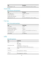
Page 98: ...21 miles 40 km 24 86 miles 40 km 24 86 miles 70 km 43 50 miles NSQ1XP20 Table 22 NSQ1XP20 specifications Item Description Memory type and size DDR2 SDRAM 1 memory slot 512 MB default expandable to 1 G...

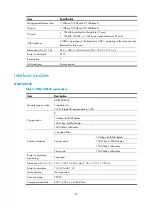
Page 99: ...Supported Dimensions H W D 45 2 399 2 436 8 mm 1 78 15 72 17 20 in Power consumption 70 2 W to 84 W Hot swapping Not supported Connector type SFP LC Compliant standards 802 3 802 3u and 802 3ab Optica...

Page 100: ...re core 15 V core ground 350 V For how to install a lightning protector for a network port see Installing a lightning protector for a network port Power strip with lightning protection optional If par...

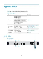
Page 101: ...NK ACT USB interface status LED USB CF card status LED CF Interface module LEDs Status LED RUN See Figure 67 Figure 68 and Figure 69 GE copper port status LED See Figure 67 and Figure 69 SFP fiber por...

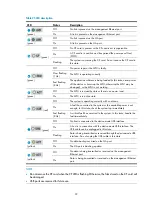
Page 102: ...On The MPU is in active state red Off The system is operating correctly with no alarms On A fault has occurred to the system or the available power is not enough In this state check the system log imm...

Page 103: ...transmitted or received at 10 100 Mbps green Off No fiber link is present on the port Steady green A fiber link is present on the port Flashing green Data is being transmitted or received at 1000 Mbp...

Page 104: ...s Description yellow green Off No link is present on the corresponding port Steady green A 1000 Mbps link is present on the port Flashing green Data is being transmitted or received at 1000 Mbps Stead...

Page 105: ...AC power module LED Figure 71 DC power module LED Table 29 LED description LED Status Description Power LED Steady green The power module is operating correctly Steady red The power module is faulty O...

Page 106: ...ay LEDs Table 30 LED description LED Status Description green Off No system power input is present or the fan tray is faulty On The fan tray is operating correctly red Off The fan tray is operating co...

Page 107: ...these interfaces are numbered Figure 73 Slot arrangement on the F5000 A5 NOTE The numbers 0 through 4 in Figure 73 represent Slot 0 through Slot 4 on the device respectively These numbers do not appe...

Page 108: ...module have the same slot number X For each type of interfaces the sequence number Y starts from 0 and increases according to the sequence on the interface module from bottom to up or from left to ri...

Page 109: ...s 100 m 328 08 ft To extend the transmission distance you can connect two twisted pair cable segments with a repeater At most four repeaters can be added which means five segments can be joined togeth...

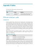
Page 110: ...cable pinouts Standard 568A pin 1 white green stripe pin 2 green solid pin 3 white orange stripe pin 4 blue solid pin 5 white blue stripe pin 6 orange solid pin 7 white brown stripe pin 8 brown solid...

Page 111: ...er cable Select an Ethernet twisted pair cable according to the RJ 45 Ethernet port type on your device An RJ 45 Ethernet interface can be MDI for routers and PCs or MDIX for switches For the pinouts...

Page 112: ...rved N A BIDD Bi directional data cable D 6 Tx Send data BIDA Bi directional data cable A 7 Reserved N A BIDC Bi directional data cable C 8 Reserved N A BIDC Bi directional data cable C To ensure norm...

Page 113: ...e classified into the following types Single mode fiber It has a core size of 10 m or smaller and has a lower modal dispersion It carries only a single ray of light It is mostly used for communication...

Page 114: ...ohol to clean the end face of the fiber connector You can brush the end face only in one direction You also need to brush the end face of the fiber port Never bend or curve a fiber when connecting it...

Page 115: ...uter diameter The curvature radius of an ordinary attached coaxial cable should be at least seven times of the cable s outer diameter If the coaxial cable is frequently bent plugged and unplugged the...

Page 116: ...along sharp edges of mechanical parts use bushings or take any other action to protect the cables from being cut or abraded The sheet metal penetration points must be smooth and fully rounded Use the...

Page 117: ...the part Cables must be protected at points where they might rub or come in contact with sharp edges or heated areas Use high temperature cables near heat sources Securely fasten cables and take adequ...

Page 118: ...es mm 10 80 to 150 10 to 30 150 to 200 30 200 to 300 Do not tie cables or bundles in a knot The metal parts of the crimped cold pressed terminal blocks such as air switch cannot protrude beyond the bl...

Page 119: ...109 Figure 83 Fiber cabling example...

Page 120: ...sion information 62 Displaying the electrical label data 64 Displaying the operating states of fans 66 E Ethernet twisted pair cable 99 Examining the installation site 2 Examples 98 F Fan failures 74...

Page 121: ...protection optional 90 Power supply system failures 73 Precautions 51 R Rebooting your firewall 69 Replacing a CF card 57 Replacing a fan tray 60 Replacing a power module 59 Replacing a transceiver m...

Reviews: