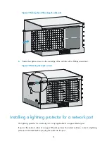
32
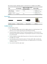
The following two types of lightning protectors for network ports are available for the F5000-A5.
Type Port
description
Maximum discharge current
(8/20
μ
s waveform)
Output voltage
10M/100M port
lightning protector
Single port
2.5 kA
•
Core-core < 15 V
•
Core-ground < 300 V
1000M port lightning
protector
Single port
3 kA
•
Core-core < 15 V
•
Core-ground < 350 V
Required tools
Flat-blade screwdriver
Phillips screwdriver
Diagonal pliers
Multimeter
Installation procedure
To install a lightning protector:
1.
Use a double-faced adhesive tape to stick the lightning protector onto the firewall chassis, and
make sure it is as close to the grounding screw of the firewall as possible.
2.
Measure the distance between the protector and the grounding screw of the firewall, cut the
ground wire of the protector as appropriate, and securely tighten the ground wire to the grounding
screw of the firewall.
3.
Use the multimeter to measure whether the ground wire of the protector contacts well with the
grounding screw of chassis.
4.
Insert the outdoor network cable into the protector's IN end, and the cable connected to the
firewall into the OUT end, and check the indicators on the lightning protector to verify that the
connection is correct.
5.
Use nylon ties to bundle the cables neatly.


