28
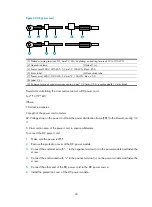
Figure 24
DC power cord
(1) Naked crimping terminal, OT, 6mm^2, M4, tin plating, naked ring terminal, 12 to 10 AWG
(2) Heat shrink tube
(3) Label 1 (+)
(4) Power cord, 600V, UL10455, 5.3 mm^2, 10AWG, black, 45 A
(5) Main label
(6) Heat shrink tube
(7) Power cord, 600 V, UL10455, 5.3 mm^2, 10AWG, blue, 45 A
(8) Label 2 (–)
(9) Common terminal, conductor cross section, 6mm^2, 20mm, 30 A, insertion depth 12 mm, black
Formula for calculating the cross section area of a DC power cord:
S=2*I*L/(57*
∆
U)
Where,
I: Current in amperes.
L: Length of the power cord in meters.
∆
V: Voltage drop on the power cord from the power distribution frame (PDF) to the firewall, usually, 3.2
V.
S: Cross section area of the power cord, in square millimeters.
To connect the DC power cord:
1.
Make sure the power is OFF.
2.
Remove the protection cover of the DC power module.
3.
Connect the end marked with “– “to the negative terminal (–) on the power module and fasten the
screw.
4.
Connect the end marked with “+“to the positive terminal (+) on the power module and fasten the
screw.
5.
Connect the other end of the DC power cord to the DC power source.
6.
Install the protection cover of the DC power module.


