100
strict application requirements and are expensive although they provide better EMI prevention
performance than UTPs, so in most LANs, UTPs are commonly used.
An Ethernet twisted pair cable connects network devices through the RJ-45 connectors at the two
ends.
shows the pinouts of an RJ-45 connector.
Figure 74
RJ-45 connector pinout diagram
NOTE:
The RJ-45 Ethernet interfaces use category 5 or higher Ethernet twisted pair cables for connection.
EIA/TIA cabling specifications define two standards, 568A and 568B, for cable pinouts.
•
Standard 568A
—pin 1: white/green stripe, pin 2: green solid, pin 3: white/orange stripe, pin 4:
blue solid, pin 5: white/blue stripe, pin 6: orange solid, pin 7: white/brown stripe, pin 8: brown
solid.
•
Standard 568B
—pin 1: white/orange stripe, pin 2: orange solid, pin 3: white/green stripe, pin 4:
blue solid, pin 5: white/blue stripe, pin 6: green solid, pin 7: white/brown stripe, pin 8: brown
solid.
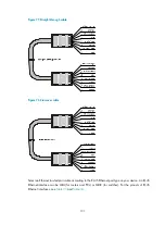
Ethernet twisted pair cables can be classified into straight-through and crossover cables based on their
pinouts:
•
Straight-through
—The pinouts at both ends comply with standard 568B, as shown in
•
Crossover
—The pinouts at one end comply with standard 568B, and those at the other end comply
with standard 568A, as shown in
.

