background image

17

24'  Batch & Autoflow

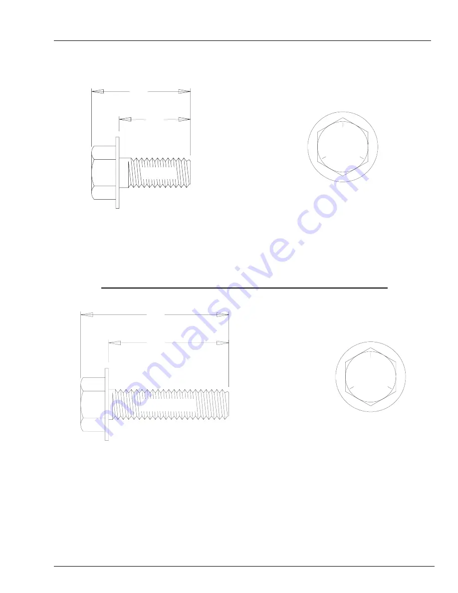
This bolt is used to connect horizontal and vertical seams for 13 gage and thinner sidewall sheets to each

other, and to bolt the stiffeners to the sidewall sheets. It is also used in attaching roof panels to the top

sidewall sheet and attaching roof panels and flashing to the center collar.

Refer to Top Dry Tank Bolting Requirements for Complete Bolt Usage

Figure #6

.950"

.750"

Top View

Side View

Grade 5

1.250"

1.437"

This bolt is primarily used to connect roof panels together where they overlap. It is also used at the

bottom of the flat bottomed bins to attach the base angle to the sidewall sheet. A small number of these

are provided for joints and FC-42076 splice plates for the stiffeners to sidewall connection.

.3125" x  1.250"

pre-assembled

with a steel backed

neoprene washer.

Top View

Grade 5

TOP DRY TANK BOLTING

.3125" x .750"
pre-assembled

with a steel

backed neoprene

washer.

S-275

Side View

S-277

Summary of Contents for PNEG-369

Page 1: ...1 24 Batch Autoflow 1 24 Batch Autoflow Construction Owners Manual PNEG 369...

Page 2: ...2 24 Batch Autoflow...

Page 3: ...LASHING INSTALLATION FLASHING BOLT INSTALLATION DISCHARGE PLATE INSTALLATION FLASHING SPLICE INSTALLATION OUTER DUMP CHUTES PULLEY ASSEMBLY DUMP CHUTE CHAIN ASSEMBLY CENTER CONE INSTALLATION CENTER CO...

Page 4: ...ONDITIONS CAN CAUSE AIR EX HAUST OR INTAKE PORTS TO FREEZE Thank you for choosing a Top Dry Series 2000 Autoflow unit It is designed to give excellent per formance and service for many years This manu...

Page 5: ...ead and understood by all people in the grain handling area The ro tating blade fire warning decals and voltage danger decal must be displayed on the fan can The bottom right decal should be present o...

Page 6: ...e of the product This product has sharp edges These sharp edges may cause serious injury To avoid injury handle sharp edges with caution and use proper protective clothing and equipment at all times G...

Page 7: ..._________________________________ _____________________________________________________________________________________________________________________ ________________________________________________...

Page 8: ...Transformer and Wiring Voltage Drop Proper Installation of Ground Rod It is very important that a Machine To Earth Ground Rod be installed at the fan This is true even if there is a ground at the pol...

Page 9: ...sheet 22 S 396 per sheet Splice Bolting Stiffener to Sidewall Bolting Per Splice 8 8 8 Per Sheet 20 2 22 S 7927 S 845 S 456 S 275 S 277 S 396 3 8 X 1 Hex Flanged 5 16 Washer 3 8 Hex Nuts 5 16 x 3 4 B...

Page 10: ...4458 Roll Caulking 2 2 2 2 2 2 S 845 5 16 Washer 75 75 100 100 125 200 Refer to stiffe ner sheets for stiffener to sidewall hardware usage Roof Hardware inserted in sidewall hardware Bin Diameter SID...

Page 11: ...int of the foundation The top of the stake should be the same height as the finished foundation will be Using one large spike nail a straight 2 x 4 approximately 2 feet longer than the radius of the b...

Page 12: ...en dug you are ready to build the forms It is important that your form be rigid enough to hold its shape against the poured concrete Also the foundation must be flat Sloped floors cannot be used in dr...

Page 13: ...d form will approximate a circle and can be constructed quite easily When the foundation form is completed install reinforcement rods by either welding or wiring in place Place 2 ofcompactedsandonthei...

Page 14: ...ter Bin NOTES Foundation site should be well drained and free of vegetation or debris Foundation design is based on a minimum soil bearing capacity of 3 000 lb ft2 If soil bearing capacity is in doubt...

Page 15: ...and stretch a pre measured chord along the imaginary circle formed by the bolt circle radius Consider the placement of these bolts so as not to interfere with the positions of bin doors and transitio...

Page 16: ...o be Grade 8 or 8 2 IMPORTANT Do not tighten bolts to exceed the torque specifications listed below HARDWARE BOLTING REQUIREMENTS TORQUE ft lb BOLT SIZE MINIMUM MAXIMUM 5 16 18 15 20 3 8 16 35 42 7 16...

Page 17: ...Complete Bolt Usage Figure 6 950 750 Top View Side View Grade 5 1 250 1 437 This bolt is primarily used to connect roof panels together where they overlap It is also used at the bottom of the flat bot...

Page 18: ...he sheet and some are used at the main eave clips The 3 8 steel flat washers S 248 are used at the stiffener splices and some are used in the roof rafter splices This bolt is used to attach the wall b...

Page 19: ...t interfere with other accessories below Roof vents should be spaced evenly around the roof Quantity will vary with individual systems NOTE The Top Dry system should be provided with a dependable equi...

Page 20: ...op and bottom Failure to observe this will not allow the door to fit properly Carefully review the erection manual and place sidewall sheets as shown Top of Sheet Bottom of Sheet Horizontal seam hole...

Page 21: ...ges 20 20 20 20 20 16 20 20 20 20 20 20 16 18 20 20 20 20 20 20 16 18 18 20 20 20 20 20 20 16 17 18 18 20 20 20 20 20 20 16 17 17 18 18 18 20 20 20 20 20 16 Door locations are shown by the underlined...

Page 22: ...2 Ring 14 Ga FC 4205714 94 19 32 Green 2 Ring 16 Ga FC 4207516 93 9 16 Blue 2 Ring 18 Ga FC 4207518 93 9 16 Orange 2 Ring 16 Ga Top FC 4206516 85 9 16 Blue 2 Ring 18 Ga Top FC 4206518 85 9 16 Orange 1...

Page 23: ...rs On the overlap of the stiffeners and on the splice use 3 8 x 1 hex bolts a washer on thee nut side connection Refer to the stiffener layout Figure 8 for stiffener usage All stiffeners are outside t...

Page 24: ...you may find that in some cases the stiffener with base plate attached will not rest on the foundation due to unlevel concrete etc Shim plates have been furnished and should be used to fill opening be...

Page 25: ...ET All bolts are standard bin bolts with neoprene washers For horizontal and vertical seam bolts the bolt head and neoprene washers are on the outside of the bin Note For the splice plates FC 42076 us...

Page 26: ...NS Horizontal Seam Horizontal Seam Horizontal Seam Horizontal Seam Horizontal Seam Even Ring Bins Odd Ring Bins 2 stiffeners per sidewall sheet Top Dry stiffener starting location 18 to 36 4 corrugati...

Page 27: ...erecting Top Dry grain bins the thinnest material always goes on top The first sidewall ring you assemble will be the second ring from the top of your bin Check the various gauges of your bin with th...

Page 28: ...location Install the flashing bolts from the outside Figure 17 SIDEWALL CONSTRUCTION INSTRUCTIONS Right Sidewall Left Sidewall Concrete Foundation Using correct size bin bolts throughout begin assembl...

Page 29: ...et s top hole matching the first hole up from the horizontal seam not counting the horizontal seam Bracket to sidewall connection using a 3 8 x 1 1 2 bolt S 2086 head outside with a neoprene washer S...

Page 30: ...Fasten the rolled C eave members to the wall brackets in the upper 2 holes of the top set of three 3 holes leaving the bolts loose Install the splice plates at the rolled C eave member seams using 3...

Page 31: ...the concrete Figure 22 8 9 1 2 Add channel braces and brace plates to center collar as shown using 3 8 x 1 bolts and nuts Do not attach cross channel until floor is done TD 100460 Channel Brace Plate...

Page 32: ...retoalternateleft right left right etc Thefloorsheetsupportpurlinscannowbeinstalledusing 5 16 x3 4 binbolts Therearetwo 2 differentlengthsofpurlinstofitbetweentherafters Insertthestraight tab of the p...

Page 33: ...ce the same direction use 5 16 x 3 4 bin bolts and nuts with the three bent edges facing toward the sidewall the longest edge on top Bolt purlins to rafters as shown in the photo in the 4th hole count...

Page 34: ...the top plate up under the bottom flange of the C channel in front of the fan opening Mark and drill four 3 8 holes into bottom flange using diffuser hangers as a guide Using 5 16 x 3 8 bolts and nuts...

Page 35: ...n bolts and nuts Position the side plates on each side with the angle outward and fasten in place using six 6 1 4 x 1 self drilling screws NOTE The corner bolt will need to be removed through the side...

Page 36: ...a flashing angle on top of the sheet across the outer edge of the hopper entrance with the interior of the angle facing the sidewall Screw down through the angle sheet and hopper with 5 16 x 3 4 self...

Page 37: ...in the floor sheet indicate the location of the leveling band posts Attach posts with 5 16 x 1 1 4 bin bolts S 277 The third hole from the bottom of the sheet there will be 7 posts 1 every third shee...

Page 38: ...LATION Install the eave flashing bolts 5 16 x 1 1 4 through the sidewall and tighten first nut Note at the vertical sidewall seams one bolt is turned around to avoid interference with eave flashing re...

Page 39: ...D 100588 Bottom Bracket for Discharge Plate Figure 33 Install the discharge plate assemblies over the flashing with a fender washer and nuts letting the bottom bracket rest against the flashing Screw...

Page 40: ...y Figure 30 TD 100647 DumpHopperAssembly S 1102 1 4 Nut 2perbolt S 1102 1 4 Nut 1perbolt S 1429 1 4 x5 8 Bolt TD 100598 AngleDam TD 100017 DumpChute Figure 31 The flashing splice pieces can now be att...

Page 41: ...de Formed View Formed Overhead View Flat Overhead View 1 4 x 5 8 Bolts Nuts TD 100219 Perforated Cone Section 6 Required Install cone over the center collar Fasten Cone Assembly with 12 10 x 3 4 self...

Page 42: ...ons in the roof hardware box WITH THE FOLLOWING EXCEPTIONS 1 Locate eave clips so that a roof sheet will be centered over sidewall ladder 2 Four eave clip shims per eave clip must be installed 3 Use T...

Page 43: ...must be installed 3 Use TD 100274 Roof Brackets shipped in the Top Dry hardware rather than the brackets shipped in the roof hardware Figure 36 Top Ring Sidewall Sheet R 007 2 Small Eave Clip TD 1000...

Page 44: ...t to each other only at endmost holes until completing the circle where an overlap may occur TD 100662 15 2 Figure 38 6 13 16 4 3 8 3 16 6 Band Sections per Ring 7 Bays w 23 Holes Between Posts TD 100...

Page 45: ...ley assembly to the cross angle in the middle of the center collar assembly Use a 3 8 x 1 hex head cap bolt to fasten assembly to the cross angle Position the pulley in the direction of the desired wi...

Page 46: ...below Install all chains using S hooks S 4692 to attach the chains to the dump chutes and lift plates Keep excess chain at the lift plate Adjust the chains until the chutes are approximately level wh...

Page 47: ...f the chutes must be limited to prevent damage on new Top Dry bins This can be done after the bin is complete and the cable stop bracket and clamp is set to indicate when the dump chutes are fully clo...

Page 48: ...Fan Adapter 28 TD 100098 Fan Adapter 24 TD 100206 Fan Adapter Blank Figure 42 42 TD 100681 Fan Entrance Sheet 42 TD100523 Transition TD 100537 Deflector 36 Fan Only 24 thru 36 Fans 42 Fans FAN ENTRANC...

Page 49: ...R WELDMENT ACD 4505 5 16 X 3 4 BOLTS 3 8 X 1 1 2 FULL THREADS ACD 4515 2 3 8 WASHERS USE AS NEEDED ACD 4510 2 3 8 X 1 BOLTS INNER DOOR ACD 4508 S 3867 2 ACD 4509 THE QUANTITY OF 3 8 WASH ERS NEEDED MA...

Page 50: ...foundation after assembling and tightening the bolts on the new ring Now rebolt the lifting straps continue ring additions until you are ready for door installation Remember to attach lifting brackets...

Page 51: ...ON OF PLATFORMS TDP 5008 Sidewall Brace Outside Ladder Access Door Platform Inside Ladder TD 100686 Small Platform Vertical Support Small Platform Optional TD 100685 Large Platform Vertical Support La...

Page 52: ...tly Now proceed to the platform floor Align holes on platform floor with holes on platform support and bolt together using 5 16 x 3 4 truss head bolt and nuts Next assemble handrail posts handrails an...

Page 53: ...0 12 TD 100686 Vertical Support 70 2 43 11 13 TD 100083 Support Channel 80 7 8 2 32 98 14 TD 100084 Knee Brace 83 5 8 2 23 67 15 TD 100090 Small Platform Hardware Package 1 8 96 For 36 Fans and Smalle...

Page 54: ...l stiffeners as shown in Figure 46 and double nut with 5 16 nuts When bolting stiffener to sidewall at locations where platform supports are to be attached use 25 5 16 x 1 1 4 bin bolts heads to insid...

Page 55: ...n Quantity Weight 1 TD 100051 Channel Bracket 10 4 87 2 TD 100052 Handrail Post 49 3 4 7 55 47 3 TD 100053 Toeboard 71 1 2 1 4 99 4 TD 100054 Toeboard 92 1 6 42 5 TD 100055 Toeboard 95 1 2 1 6 67 6 TD...

Page 56: ...n bolts heads to inside Start 12 inches below horizontal seam of second and third rings from top See Figure 46 LARGE PLATFORM ASSEMBLY CONT Figure 52 10 12 11 13 1 Position the vertical support to the...

Page 57: ...assembling the platform support that the support brace is placed correctly Now proceed to the platform floor Align holes on platform floor with holes on platform support and bolt together using 5 16 x...

Page 58: ...spaced TD 100545 3 Perforated Band Figure 54 Roof Sheet PERFORATED CENTER BAND Drill 6 3 8 diameter holes equally spaced as shown above for top band clips Attach clips using 5 16 x 3 4 bin bolts Add p...

Page 59: ...ySwitch Optional High or Low Limit Rotary Switch ROTARY SWITCH PANEL LOCATION Drill 2 diameter holes through roof panels at locations shown on previous page Use a mounting plate as a pattern and drill...

Page 60: ...x 1 1 4 Cotter Pin 2 0 02 INSTALLATION OF ROOF MOUNTED LEVEL SWITCH Drill 2 diameter holes through roof panels at locations shown on previous page Use a mounting plate as a pattern and drill 4 3 8 ho...

Page 61: ...ALLATION OF WALL MOUNTED ROTARY SWITCHES Note Wall mounted switch must be located at least 3 below the fan opening Drill 2 hole through wall 3 below the upper fan and heating unit s IF BIN IS 2 66 cor...

Page 62: ...lledcouplingandpaddle Note singlevanepaddleisusedon Lowlevelswitch Also besuretouserollpinswheninstructed Ifcotterpinsareused bend backfullytoeduceshaftguardinterferencetorotation Key Part No Descript...

Page 63: ...N TR 4734 BEFORE CUTTING THE OPENING CHECK THAT TR 4734 IS THE TRANSITION THAT WAS ORDERED When installing the GSI aeration transition it will be necessary to field cut a hole into the bottom sidewall...

Page 64: ...inside of tran sition sides Hardware Package not shown Included in Hardware Package Key Part Number Description 1 TR 4724 1 Transition side 1 TR 4724 2 Transition side 2 TR 4767 Transition faceplate 3...

Page 65: ...r illustration instructions with hinges Note do not distort door frame with use of alignment or drift punches if necessary drill or ream holes to insert bolts in door frame Now tighten frame bolts sta...

Page 66: ...66 24 Batch Autoflow TWO RING DOOR ASSEMBLY DOOR HOLD BACK DETAIL DOOR FRAME ASSEMBLY Figure 62...

Page 67: ...ER DOOR HINGE WD 6054 WD 6054 1 1 11 RUBBER TRIM SEAL STRIP S 4380 S 4380 2 1 4 FT 2 1 4 FT 12 LATCH BAR WD 6039 WD 6039 3 3 13 INNER PANEL LATCH RIGHT HAND WD 6037 WD 6037 3 3 14 INNER PANEL LATCH LE...

Page 68: ...68 24 Batch Autoflow Figure 63 Center bin step under door WD 041 2 WD 1984 WD 041 1 Field drill holes in sidewall sheet on ridge of corrugation OPTIONAL BIN STEP ASSEMBLY WD 042...

Page 69: ...as been placed and secured continue adding necessary sidewall ring s To the lower edge of the bottom ring attach the base angle ring Before lowering the bin apply mastic sealer to the entire underneat...

Page 70: ...rmostat as shown in Figure 58 Important Do not mount the thermostat between the fans on a 2 fan system 2 Use template supplied to cut hole in sidewall 3 Apply rope caulk to sides and top of plastic ho...

Page 71: ...RODUCTS GSI SHALL NOT BE LIABLE FOR ANY DIRECT INDIRECT INCIDENTAL OR CONSEQUENTIAL DAMAGES INCLUDING WITHOUT LIMITATION LOSS OFANTICIPATED PROFITS OR BENEFITS PURCHASER S SOLE AND EXCLUSIVE REMEDY IS...

Page 72: ...72 24 Batch Autoflow 1004 E Illinois St Assumption IL 62510 Phone 217 226 4421 Fax 217 226 4498 March 1998...

Reviews: