Smart SVC Relay Instruction Manual
41
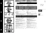
Figure 3.95
ÖRNEK:
If parameter is 10, the inductive power is accepted 10% more than the measured
power. So, 80 kW power is accepted as 80 + 80 x 10%=88. If it is – 10, it is reversed.
Thus, it is 80-80x1%0=72.
Cp Off Set Fac L1, L2, L3
It determines % multiplier of the measured capacitive power to be added.
Figure 3.96
EXAMPLE:
If parameter is 10, the capacitive power is accepted 10% more than the measured
power. So, 80 kW power is accepted as 80 + 80 x 10%=88. If it is – 10, it is reversed.
Thus, it is 80-80x1%0=72.
Normal Effect
It stabilizes the solution found with SVC.
Figure3.97
Ignore Mode
If one or two of the phases changed directions, it is used to bypass the compensation of the
wanted direction.
Figure 3.98
LC Force Fac
It used to direct the system to capacitive or move away from capacitive.
In Off Set Fac L1,L2,L3
0
Cp Off Set Fac L1,L2,L3
0
Normal Effect
Off
Ignore mod
Off
LC force Fac
Off
Summary of Contents for SMART GES1
Page 10: ...Smart SVC Relay Instruction Manual 10 1 4 1 SMART S12 1 4 Connection Diagrams...
Page 11: ...Smart SVC Relay Instruction Manual 11 1 4 2 SMART S18...
Page 12: ...Smart SVC Relay Instruction Manual 12 1 4 3 SMART S18 T...
Page 13: ...Smart SVC Relay Instruction Manual 13 1 4 4 SMART SOG1 SOG5...
Page 14: ...Smart SVC Relay Instruction Manual 14 1 4 5 SMART GES1 GES5...