Viale Caduti per la Libertà, 4b - 40050 MONTE S. PIETRO - BOLOGNA (ITALY) –
Tel. 051/6761552 - Internet: http://www.emirelsrl.it - E-mail: [email protected] – [email protected]
1
Release 17/03/22
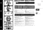
W 17 LIMITATORE DI CARICO
Multigamma, a inserzione diretta fino a 40A
(22kW-400V)
(Non è prevista l'applicazione con INVERTER o SOFT
START)
Il dispositivo può considerarsi l'evoluzione dell'E404-1,
conforme alla NORMA: EN 15011 : 2011.
“BASSA TENSIONE" - LVD CEI-EN 61010-1
COMPATIBILITA' ELETTRO MAGNETICA CEI-EN 61326-1
DEFINIZIONE
Controlla la potenza attiva assorbita da un motore a 2
polarità (o 2 velocità) oppure da 2 motori a una polarità,
oppure un motore ad 1 polarità.
UTILIZZAZIONE
Applicato per il controllo e la limitazione del carico sollevato,
al posto delle CELLE di CARICO.
CARATTERISTICHE E REGOLAZIONI
Il frontale è diviso in due zone, a sinistra c'è la zona dedicata
alla marcia LENTA, a destra c'è la zona dedicata alla marcia
VELOCE.
I settaggi e le regolazioni presenti nella sezione L - Lenta
sono: a, b, TCL, INL e DSL.
I settaggi e le regolazioni presenti nella sezione V - Veloce
sono: a, b, TCV, INV e DSV.
Il tempo di ritardo TR non ha regolazione esterna.
"
a
" Soglia di intervento impostabile a cacciavite, divisa in
10 parti. Alla tacca "10" corrisponde il fondo scala (in
potenza attiva) della GAMMA scelta con l'attivazione
del DSL (o DSV). Questa soglia è disabilitata durante il
tempo impostato con TCL (o TCV). Questi timer si
attivano quando la (I) supera la Im della gamma scelta.
I valori impostabili con “aL” ed “aV” possono essere
controllati con un tester in Vdc, nei due morsetti point
posti sul fronte del dispositivo (10Vdc max).
I due punti della morsettiera sul frontale (aL, aV) sono
uscite analogiche. L’operatore deve fare i collegamenti a
dispositivo non alimentato e avendo controllato di non
essere carico di elettricità statica. (E’ stata apposta
l’etichetta nera Sensitive to “ESD” - ESD=Electrostatic
Discharge).
"
b
" Soglia di intervento che può essere uguale ad "a" o
superiore ad "a" fino al 5%. Questa soglia non è
disabilitata da alcun timer. Si veda Fig. 2, riconosce la
presenza di un picco di carico (troppo elevato) per cui
viene fermato istantaneamente.
TCL / TCV
Tempo di "cecità" regolabile a cacciavite (0,1÷1s) che
disabilita la soglia di intervento "a" alla partenza del
motore (quando la I supera la Im della gamma scelta).
TR
Tempo di ritardo (1s. fisso, non accessibile) che ritarda
la partenza della VELOCE per permettere alla soglia "a"
W 17 LOAD LIMITER
Multirange, direct insertion up to 40A (22kW-
400V)
(No Application with INVERTER or SOFT START)
The device is the evolution of E404-1 developed,
complying with STANDARD : EN 15011 : 2011.
LVD - "LOW VOLTAGE" CEI-EN 61010-1
ELECTROMAGNETIC COMPATIBILITY CEI-EN 61326-1
FUNCTION
It monitors the active power absorbed by a 2 pole motor
(or 2 speeds motor), or two motors with one speed, or one
motor with one speed.
USE
Applied for monitoring and limiting the hoisted load, in
place of LOAD CELLS.
CHARACTERISTICS AND REGULATIONS
The front panel is divided in two sections: the section on
the left is for the SLOW operation, section on the right is
for the FAST operation.
The settings and adjustments of section L (SLOW) are: a,
b, TCL, INL e DSL.
The settings and adjustments of section V (FAST) are: a,
b, TCV, INV e DSV.
The Delay Time TR has no external regulation
"
a
" Triggering set point, set by screwdriver, divided in 10
parts. The tick mark "10" corresponds to the full scale
(expressed in active power) of the range which has
been activated through DSL or DSV. This set point is
disabled during the time set by TCL or TCV. These
timers are active when (I) overcomes Im of the
selected range.
The values which can be set through “aL” ed “aV” can
be checked by a Vdc tester on the two terminals on
the front of the device (10Vdc max).
The two terminals on the front (aL, aV) are analogic
outputs. The operator must make the wirings when the
device is “not supplied” and must be sure not to be
charged with static electricity (See the black label:
Sensitive to “ESD”).
"
b
" Triggering set point which may be of the same value
or up to 5% higher than “a”. No timer disables this set
point.
Make ref to Fig.2, it detects a too high peak of load
and it stops hoisting immediately.
TCL / TCV
Delay time, adjustable by screw driver (0,1÷1s); it
disables the triggering set point “a” at the motor start
up. (when I overcomes Im of the selected range).
TR
Delay time (1s. fixed, not adjustable) delaying
start up of the FAST operation in view of allowing that the
A
T
T
E
N
Z
IO
N
E
:
V
e
rr
a
n
n
o
ri
p
a
ra
ti
i
n
g
a
ra
n
zi
a
,
fra
n
co
n
s
se
d
e
,
i
d
is
p
o
si
ti
vi
g
u
a
st
i
p
e
r
d
if
et
ti
s
u
i
m
a
te
ri
a
li,
e
n
tr
o
2
4
me
si
d
a
lla
d
a
ta
d
i
co
n
se
g
n
a
.
E
m
ir
e
l
n
o
n
è
i
n
a
lc
u
n
c
a
so
r
e
sp
o
n
sa
b
ile
p
e
r
d
a
n
n
i,
d
ir
e
tt
i
o
i
n
d
ir
e
tt
i,
a
p
e
rs
o
n
e
o
c
o
se
,
ch
e
d
e
ri
va
n
o
d
a
:
ma
n
ca
to
f
u
n
zi
o
n
a
me
n
to
,
ma
n
o
mi
ss
io
n
i,
u
so
e
rr
a
to
o
d
i
mp
ro
p
ri
o
d
e
i
p
ro
p
ri
d
is
p
o
si
ti
vi
d
i
P
ro
te
zi
o
n
e
e
C
o
n
tr
o
llo
.
P
e
r
le
a
p
p
lic
a
zi
o
n
i
"i
n
S
IC
U
R
E
Z
Z
A
"
si
c
o
n
si
g
lia
l
'u
so
d
i
si
st
e
m
i
d
i
S
IC
U
R
E
Z
Z
A
o
l
'u
so
d
i
te
cn
ic
h
e
d
i
"R
ID
O
N
D
A
N
Z
A
".
W
A
R
N
IN
G
:
R
e
p
ai
rs
i
n
g
u
a
ra
n
te
e
a
re
m
a
d
e
f
re
e
o
u
r
fa
ct
o
ry
,
w
it
h
in
2
4
mo
n
th
s
fr
o
m
th
e
d
e
liv
e
ry
d
a
te
,
fo
r
th
e
d
e
vi
ce
s
n
o
t
w
o
rk
in
g
d
u
e
to
d
e
fe
ct
s
o
f
th
e
c
o
mp
o
n
e
n
ts
.
In
n
o
c
a
se
E
mi
re
l
ca
n
b
e
h
e
ld
re
sp
o
n
si
b
le
f
o
r
d
a
m
a
g
e
s,
d
ir
e
ct
o
r
in
d
ir
e
ct
,
o
cc
u
rr
e
d
t
o
t
h
in
g
s
o
r
p
e
o
p
le
i
n
c
o
n
se
q
u
e
n
ce
o
f
w
ro
n
g
c
o
n
n
e
ct
io
n
s,
a
cc
id
e
n
ts
,
n
o
t
co
rre
ct
u
se
o
r
n
o
t
o
p
er
a
ti
o
n
o
f
th
e
P
ro
te
ct
io
n
a
n
d
C
o
n
tr
o
l
d
e
vi
ce
s
o
f
it
s
o
w
n
p
ro
d
u
ct
io
n
.
F
o
r
th
e
"
sa
fe
ty
a
p
p
lic
a
ti
o
n
s"
,
it
i
s
su
g
g
e
st
e
d
t
o
a
p
p
ly
S
A
F
E
T
Y
s
ys
te
m
s
o
r
R
E
D
U
N
D
A
N
C
Y
e
n
g
in
ee
ri
n
g
."
.