Pilz PNOZ X9, Operating Manual
The "Pilz PNOZ X9" is a reliable and safe safety relay system designed for various industrial applications. For easy and convenient operation, we provide a comprehensive "Operating Manual" that can be downloaded for "free" from our website. Get your "manual" today at manualshive.com and unlock the full potential of this exceptional product.
Share
Download


Reviews:
No comments
Related manuals for PNOZ X9

STW1000V2
Brand: ZIEHL Pages: 6

SNO 2004K
Brand: Wieland Pages: 16

BIS-412M 24V
Brand: F&F Pages: 7

MFAC 14
Brand: GE Pages: 25

MLJ
Brand: GE Pages: 42

MDP
Brand: GE Pages: 68

MOV 2000
Brand: GE Pages: 78

MOTOR MANAGEMENT RELAY 469
Brand: GE Pages: 311

MiCOM P40 Agile P14D
Brand: GE Pages: 12

SEL-487V
Brand: Schweitzer Engineering Laboratories Pages: 32

Soft Touch Relay Bypass
Brand: MAS Pages: 4

ELD V2
Brand: Ampcontrol Pages: 19
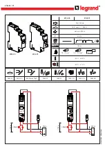
CX3
Brand: LEGRAND Pages: 2

001DC009AC
Brand: CAME Pages: 12

HR6S Series
Brand: IDEC Pages: 36

EDR-5000
Brand: Eaton Pages: 1017

ZE/XTOM Series
Brand: Eaton Pages: 64

ESR5-NZ-21-24VAC-DC
Brand: Eaton Pages: 19


