background image

Schweitzer Engineering Laboratories, Inc.

SEL-487V Data Sheet

Capacitor Bank Protection,

Automation, and Control

Major Features and Benefits

The SEL-487V Capacitor Bank Protection, Automation,
and Control System integrates voltage or reactive power
control for grounded and ungrounded capacitor banks
with full automation and protection in one device.

Protects Grounded and Ungrounded Banks.

The SEL-487V provides sensitive voltage differen-
tial or current unbalance protection with compen-
sation adjustment. The compensation adjustment is
used to zero out small unbalances that are natural
in the bank as well as instrument transformer
errors. Instantaneous and time-overcurrent ele-
ments and voltage elements provide additional pro-
tection for the capacitor bank. The SEL-487V
provides breaker failure protection for the capaci-
tor bank breaker using high-speed (less than one
cycle) open-pole detection logic that reduces coor-
dination times for critical breaker failure applica-
tions.

Control. 

The SEL-487V-1 is available with control

functions for maintaining system voltage, VAR or
power factor (PF) levels, and reactor loading. The
control functions include auto/manual and

local/remote control capabilities with control insta-
bility detection for alarm or blocking of control
operations. Implement the time-of-day control fea-
ture to synchronize capacitor bank insertion with
peak VAR demand periods for any weekday or
weekend period. Automatically sequence as many
as three capacitor bank stages by using the univer-
sal sequencing control. This control provides
sequencing based upon accumulated operating
time, an analog quantity, or a fixed order.

Automation.

 Take advantage of enhanced automa-

tion features that include 32 programmable ele-
ments for local control, remote control, protection
latching, and automation latching. Local metering
and control on the large format front-panel liquid
crystal display eliminates the need for separate
panel meters and switches. Serial and Ethernet
links efficiently transmit key information, includ-
ing:

Metering data

Protection element and control I/O status

IEEE C37.118 synchrophasors
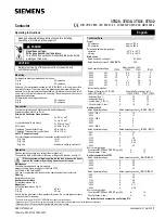
SEL-487V Relay

Summary of Contents for SEL-487V

Page 1: ... applica tions Control The SEL 487V 1 is available with control functions for maintaining system voltage VAR or power factor PF levels and reactor loading The control functions include auto manual and local remote control capabilities with control insta bility detection for alarm or blocking of control operations Implement the time of day control fea ture to synchronize capacitor bank insertion wi...

Page 2: ...mation systems using IEC 61850 or DNP3 proto col directly Optionally connect to DNP3 networks through an SEL 2032 Communications Processor File transfer protocol FTP is provided for high speed data collection Connect to substation or cor porate LANs to transmit synchrophasors in the IEEE C37 118 2005 format using TCP or UDP Internet protocols Simple Network Time Protocol SNTP The relay shall be ca...

Page 3: ...erential 3 LOP Loss of Potential 2 ANSI NUMBERS ACRONYMS AND FUNCTIONS 27P 27 P Q B 32 P G 37C 46P 49 50BF 50FO 50 P G Q 51 P G Q 59 P G B 60 60N 60P 67 P G Q 81 O U R 85 RIO 87V 87VN DFR HMI LGC MET PMU RTU SER ADDITIONAL FUNCTIONS BRM LDP 1 Copper or Fiber Optic Optional Feature Phase Undervoltage Undervoltage Phase Neg Seq Bank Real and Reactive Power Phase Ground Undercurrent Phase Current Unb...

Page 4: ...to line switching operations Neutral Voltage Differential Elements Figure 3 Neutral Voltage Differential One Line Diagram The SEL 487V provides three neutral voltage differential elements for protection of up to three ungrounded wye capacitor banks The neutral voltage differential elements of the SEL 487V calculate zero sequence voltage from the three phase potential inputs provided from the line ...

Page 5: ...currents The relay offers three levels of phase negative and zero sequence overcurrent protection for the W terminal current inputs Torque control is provided for each element The SEL 487V also includes ten selectable operating quantity inverse time overcurrent elements You can select the operating quantities from the following IA IB IC MAX IA IB IC where IA IB IC can be funda mental or rms quanti...

Page 6: ...A or 5 A The FAULT Relay Word is asserted The circuit breaker has been closed open phase detection element has deasserted for a settable dropout period Breaker Failure Protection Incorporated into the SEL 487V is a full function breaker failure system High speed open pole detection logic allows you to set the pickup current below minimum load for sensitivity without sacrificing high speed dropout ...

Page 7: ...SCII commands SELOGIC control equations Fast Operate messages and from the one line diagram The one line diagram includes user configurable apparatus labels and as many as six user definable analog quantities One Line Bay Diagrams The SEL 487V offers a variety of preconfigured one line diagrams for common bus and capacitor bank configurations Once a one line diagram is selected the user has the ab...

Page 8: ...gs with the ACSELERATOR QuickSet settings interface The standard style settings are displayed in traditional form under the relay form ACSELERATOR QuickSet also provides an interactive relay setting entry method The interactive method works by clicking on the one line diagram labels This action automatically displays all the settings for the device selected This method provides an easy way of orga...

Page 9: ...Front Panel Display The liquid crystal display LCD shows event metering settings and relay self test status information The target LEDs display relay target information as described in Figure 8 and explained in Table 4 The LCD is controlled by the navigation pushbuttons Figure 9 automatic messages the relay generates and user programmed analog and digital display points The rotating display scroll...

Page 10: ...splay Points Create custom screens showing metering values special text messages or a mix of analog and status information Figure 11 shows an example of how display points can be used to show circuit breaker information and current metering As many as 96 display points can be created All display points occupy only one line on the display at all times The height of the line is programmable as eithe...

Page 11: ...ol independent of the relay The auxiliary trip close pushbuttons are electrically separate from the relay operating even if the relay is powered down Make the extra connections at Terminals 201 through 208 See Figure 21 through Figure 22 for a rear panel view Figure 13 shows one possible set of connections The auxiliary trip close pushbuttons incorporate an arc suppression circuit for interrupting...

Page 12: ...porting In response to a user selected internal or external trigger the voltage current and element status information contained in each event report confirms relay scheme and system performance for every fault Decide how much resolution analog data are necessary when an event report is triggered 8 kHz 4 kHz 2 kHz or 1 kHz The relay stores from 24 seconds of data per fault at 1 kHz resolution to 3...

Page 13: ...profile report provides a comma separated variable CSV list that can be loaded into any spreadsheet or database for analysis and graphical display SELOGIC enable disable functions can start and stop signal profiling based on Boolean or analog comparison conditions High Accuracy Timekeeping With a combination of IRIG B and a global positioning satellite the SEL 487V time tags oscillography to withi...

Page 14: ...and Settings Automation Flexible Control Logic and Integration Features SEL 487V control logic Replaces traditional panel control switches Eliminates RTU to bay wiring Replaces traditional latching relays Replaces traditional indicating panel lights Performs real time control using synchrophasor data Eliminate traditional panel control switches with 32 local control points Set clear or pulse local...

Page 15: ... to your logic functions Programming SELOGIC control equations consists of combining relay elements inputs and outputs with SELOGIC control equation operators Table 7 Any element in the Relay Word can be used in these equations The SEL 487V is factory set for use without additional logic in most situations For complex or unique applications these expanded SELOGIC functions allow superior flexibili...

Page 16: ...perating in the MIRRORED BITS communications mode Communicated information can include digital analog and virtual terminal data Virtual terminal allows the operator access to remote relays through the local relay MIRRORED BITS port These MIRRORED BITS can be used to transfer information between the SEL 487V and other system voltage regulation devices to provide enhanced system voltage and power fa...

Page 17: ...ion sessions Telnet can access relay settings as well as metering and event reports remotely using the ASCII interface Transfer settings files to and from the relay via the high speed Ethernet port with FTP IEEE C37 118 Synchrophasors The latest IEEE synchrophasor protocol provides a standard method for communicating synchronized phasor measurement data over Ethernet or serial media The integrated...

Page 18: ...an data and desig nated remote analog outputs are provided with 3 ms latency from device to device Apply outgo ing GOOSE messages for high speed control and monitoring of external breakers switches and other devices IEC 61850 Data Server The SEL 487V equipped with embedded IEC 61850 Ethernet protocol pro vides data according to predefined logical node objects As many as six simultaneous client ass...

Page 19: ...logic and general indication Each control output is programmable using SELOGIC control equations One board can be added to the 4U chassis and two additional I O boards can be added to the 5U chassis Breaker Control The SEL 487V contains analog voltage inputs for multiple sources and control inputs to indicate both breaker and disconnect position as well as the logic required to provide breaker con...

Page 20: ...er Engineering Laboratories Inc 20 Front and Rear Panel Diagrams Figure 19 Typical SEL 487V Horizontal Front Panel Diagrams i4453a i4454b 4U Horizontal Rack Mount With Auxiliary Trip and Close Pushbuttons 5U Horizontal Panel Mount ...

Page 21: ... Engineering Laboratories Inc SEL 487V Data Sheet 21 Figure 20 Typical SEL 487V Vertical Front Panel Diagrams 4U Vertical Rack Mount 5U Vertical Panel Mount With Auxiliary Trip and Close Pushbuttons i4455b i4456b ...

Page 22: ...L 487V Data Sheet Schweitzer Engineering Laboratories Inc 22 Figure 21 4U Rear Panel Options 4U With INT2 I O Interface Board 4U With Main Board and No I O Interface Board 4U With INT4 I O Interface Board ...

Page 23: ...torized With INT3 and INT8 Interface Boards and Ethernet Option Relay Dimensions Figure 23 SEL 487V Dimensions for Rack and Panel Mount Models Horizontal Mounting Shown Dimensions Also Apply to Vertical Mounting 5U Connectorized With INT3 and INT8 Interface Boards and Ethernet Option ...

Page 24: ...VA at 1 A 5 A Nominal 0 5 VA at 5 A AC Voltage Inputs Three phase four wire wye connections are supported Rated Voltage Range 55 250 VLN Operational Voltage Range 0 300 VLN Ten Second Thermal Rating 600 Vac Burden 0 1 VA 125 V Frequency and Rotation Nominal Frequency Rating 50 5 Hz 60 5 Hz Phase Rotation ABC or ACB Frequency Tracking Range 40 65 Hz 40 Hz 40 Hz 65 Hz 65 Hz Maximum Slew Rate 15 Hz s...

Page 25: ...up 105 150 Vdc Dropout 75 Vdc 220 Vdc Pickup 176 264 Vdc Dropout 132 Vdc 250 Vdc Pickup 200 300 Vdc Dropout 150 Vdc Current Draw 5 mA at nominal voltage 8 mA at 110 V option Rated Frequency 50 5 Hz 60 5 Hz AC Thresholds Ratings Met Only When Recommended Control Input Settings Are Used See Table 2 1 48 Vac Pickup 32 8 60 0 Vac rms Dropout 20 3 Vac rms 110 Vac Pickup 75 1 132 0 Vac rms Dropout 46 6 ...

Page 26: ... wiring regulations Type Tests Installation Requirements Overvoltage Category 3 Pollution Degree 2 Safety Product Standards IEC 60255 27 2013 IEEE C37 90 2005 21 CFR 1040 10 Dielectric Strength IEC 60255 27 2013 Section 10 6 4 3 2 5 kVac 50 60 Hz for 1 min Analog Inputs Contact Outputs Digital Inputs 3 6 kVdc for 1 min Power Supply Battery Monitors 2 2 kVdc for 1 min IRIG B 1 1 kVdc for 1 min Ethe...

Page 27: ...s IEC 60255 26 2013 Section 7 1 Class A 47 CFR Part 15B Class A Canada ICES 001 A NMB 001 A Environmental Product Standards IEC 60255 27 2013 Cold Operational IEC 60068 2 1 2007 Test Ad 16 hours at 40 C Cold Storage IEC 60068 2 1 2007 Test Ad 16 hours at 40 C Dry Heat Operational IEC 60068 2 2 2007 Test Bd 16 hours at 85 C Dry Heat Storage IEC 60068 2 2 2007 Test Bd 16 hours at 85 C Damp Heat Cycl...

Page 28: ...5 per unit Time Delay Range 0 00 400 0 s Reset Time Range 0 00 400 00 s Time Delay Accuracy 0 1 4 2 ms at 60 Hz Torque Control SELOGIC control equation Three Phase Current Unbalance Elements Number of Elements 3 W current channels only Pickup Range 0 00 to 2 00 per unit INOM Pickup Accuracy Steady State 1 of set point Maximum Pickup Dropout Time 1 5 cycles Time Delay Range 0 00 400 0 s Time Delay ...

Page 29: ... Range 3 phase OFF 1 900 W secondary in 1 W steps Single phase OFF 0 30 900 W secondary in 0 1 W steps Pickup Accuracy 3 of setting and 5 W power factor 0 5 at nominal frequency Time Delay Range 0 16 000 cycles 0 125 cycle increment Time Delay Accuracy 0 1 of setting 0 125 cycle Bay Control Breakers 1 Disconnects Isolators 10 maximum Timers Setting Range 1 99999 cycles 1 cycle steps Time Delay Acc...

Page 30: ...gnitude Accuracy at 20 C and Nominal Frequency 0 2 0 5 mA Unbalance Metering Quantity Differential Voltage dVA dVB dVC dVG1 dVG2 dVG3 Accuracy 1 0 Range 0 01 V to 100 00 V Quantity Unbalance Current 60N 60P Magnitude Accuracy 0 3 Phase Accuracy 0 3 Current Range at 0 001 to 5 000 INOM K Compensation Factors Magnitude Accuracy 1 0 0 002 KSET Phase Angle Accuracy 0 3 Optional RTD Elements RTD Temper...

Page 31: ...cle dur Medium 1 sample cycle 176 cycle dur Slow 1 sample 64 cycles 4096 cycle dur Daily 1 sample day Indefinite Control Functions SEL 487V 1 Voltage Control Dead Band Range 10 00 300 00 V sec Dead Band Control Delay 1 6000 s Stall Time Delay 1 6000 s Power Factor Control Dead Band Range 0 01 0 99 Dead Band Control Delay 1 6000 s Stall Time Delay 1 6000 s Minimum Operating Power 1 W or 1 VAR sec V...

Page 32: ...and international copyright and patent laws in its products including without lim itation software firmware and documentation The information in this document is provided for informational use only and is subject to change without notice Schweitzer Engineering Laboratories Inc has approved only the English language document This product is covered by the standard SEL 10 year warranty For warranty ...

Reviews: