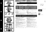
background image

806766A5.CDR

SR469 IN SERVICE

STOPPED

R1 TRIP

SETPOINT ACCESS

STARTING

R2 AUXILIARY

COMPUTER RS232

RUNNING

R3 AUXILIARY

R4 ALARM

R5 BLOCK START

R6 SERVICE

MESSAGE

HOT RTD

LOSS OF LOAD

469

Motor Management Relay

®

PROGRAM PORT

SETPOINT

7

8

9

4

5

6

1

2

3

.

0

HELP

MESSAGE

VALUE

ACTUAL

ESCAPE

ENTER

RESET

NEXT

RESET
POSSIBLE

COMPUTER RS485

AUXILIARY RS485

LOCKOUT

SR469 STATUS

MOTOR STATUS

OUTPUT RELAYS

OVERLOAD PICKUP

UNBALANCE PICKUP

GROUND PICKUP

R

E G

I S T E R

E D

469

MOTOR MANAGEMENT RELAY

®

Instruction Manual

469 Firmware Revision: 30E281.000

469PC Software Revision: 2.8x

Manual P/N: 1601-0057-D9 (GEK-106289A)

Copyright © 2001 GE Power Management

GE Power Management

215 Anderson Avenue, Markham, Ontario 

Canada L6E 1B3

Tel: (905) 294-6222   Fax: (905) 294-8512

Internet: http://www.GEindustrial.com/pm

Manufactured under an

ISO9001 Registered system.

g

GE Power Management

Summary of Contents for MOTOR MANAGEMENT RELAY 469

Page 1: ...RS485 AUXILIARY RS485 LOCKOUT SR469 STATUS MOTOR STATUS OUTPUT RELAYS OVERLOAD PICKUP UNBALANCE PICKUP GROUND PICKUP R E G I S T E R E D 469 MOTOR MANAGEMENT RELAY Instruction Manual 469 Firmware Revision 30E281 000 469PC Software Revision 2 8x Manual P N 1601 0057 D9 GEK 106289A Copyright 2001 GE Power Management GE Power Management 215 Anderson Avenue Markham Ontario Canada L6E 1B3 Tel 905 294 6...

Page 2: ......

Page 3: ...ce Should further information be desired or should particular problems arise which are not covered sufficiently for the purchaser s purpose the matter should be referred to the General Electric Company To the extent required the products described herein meet applicable ANSI IEEE and NEMA standards but no such assurance is given with respect to local codes and ordinances because they vary greatly ...

Page 4: ......

Page 5: ...NPUTS 2 12 2 2 7 VOLTAGE INPUTS 2 13 2 2 8 DIGITAL INPUTS 2 13 2 2 9 ANALOG INPUTS 2 14 2 2 10 ANALOG OUTPUTS 2 14 2 2 11 RTD SENSOR CONNECTIONS 2 15 a DESCRIPTION 2 15 b REDUCED RTD LEAD NUMBER APPLICATION 2 16 c TWO WIRE RTD LEAD COMPENSATION 2 17 d GROUNDING OF RTDs 2 17 2 2 12 OUTPUT RELAYS 2 18 2 2 13 DRAWOUT INDICATOR 2 19 2 2 14 RS485 COMMUNICATIONS PORTS 2 20 2 2 15 TYPICAL 2 SPEED MOTOR W...

Page 6: ...4 16 4 4 3 TEST SWITCH 4 16 4 4 4 EMERGENCY RESTART 4 16 4 4 5 REMOTE RESET 4 16 4 4 6 STARTER STATUS 4 17 4 4 7 ASSIGNABLE DIGITAL INPUTS 4 17 4 4 8 DIGITAL INPUT FUNCTION REMOTE ALARM 4 18 4 4 9 DIGITAL INPUT FUNCTION REMOTE TRIP 4 18 4 4 10 DIGITAL INPUT FUNCTION SPEED SWITCH TRIP 4 19 4 4 11 DIGITAL INPUT FUNCTION LOAD SHED TRIP 4 19 4 4 12 DIGITAL INPUT FUNCTION PRESSURE SWITCH ALARM 4 19 4 4...

Page 7: ...E 4 48 4 7 5 CURRENT UNBALANCE 4 49 a FUNCTION 4 49 b EXAMPLE 4 49 4 7 6 GROUND FAULT 4 50 4 7 7 PHASE DIFFERENTIAL 4 52 4 8 S7 MOTOR STARTING 4 8 1 ACCELERATION TIMER 4 53 4 8 2 START INHIBIT 4 54 a FUNCTION 4 54 b EXAMPLE 4 54 4 8 3 JOGGING BLOCK 4 55 a FUNCTION 4 55 b STARTS HOUR 4 55 c TIME BETWEEN STARTS 4 55 4 8 4 RESTART BLOCK 4 56 4 9 S8 RTD TEMPERATURE 4 9 1 RTD TYPES 4 57 4 9 2 RTDS 1 TO...

Page 8: ...85 4 14 4 TEST OUTPUT RELAYS 4 86 4 14 5 TEST ANALOG OUTPUT 4 86 4 14 6 COMM PORT MONITOR 4 87 4 14 7 MULTILIN USE ONLY 4 87 4 15 S14 TWO SPEED MOTOR 4 15 1 DESCRIPTION 4 88 4 15 2 SPEED2 O L SETUP 4 88 4 15 3 SPEED2 UNDERCURRENT 4 90 4 15 4 SPEED2 ACCELERATION 4 91 5 ACTUAL VALUES 5 1 OVERVIEW 5 1 1 ACTUAL VALUES MESSAGES 5 1 5 2 A1 STATUS 5 2 1 MOTOR STATUS 5 2 5 2 2 LAST TRIP DATA 5 3 5 2 3 ALA...

Page 9: ... MODBUS FUNCTIONS 6 2 1 OVERVIEW 6 4 6 2 2 FUNCTION CODES 01 02 READ RELAY COIL DIGITAL INPUT STATUS 6 4 a FUNCTION 01 6 4 b FUNCTION 02 6 4 c MESSAGE FORMAT AND EXAMPLE FUNCTION 01 6 5 d MESSAGE FORMAT AND EXAMPLE FUNCTION 02 6 6 6 2 3 FUNCTION CODES 03 04 READ SETPOINTS ACTUAL VALUES 6 8 6 2 4 FUNCTION CODE 05 EXECUTE OPERATION 6 9 6 2 5 FUNCTION CODE 06 STORE SINGLE SETPOINT 6 10 6 2 6 FUNCTION...

Page 10: ... TEST 7 12 7 3 5 SHORT CIRCUIT TEST 7 13 8 469 PC SOFTWARE 8 1 INSTALLATION UPGRADE 8 1 1 DESCRIPTION 8 1 8 1 2 HARDWARE SOFTWARE REQUIREMENTS 8 1 8 1 3 CHECKING IF INSTALLATION UPGRADE IS REQUIRED 8 2 8 1 4 INSTALLING UPGRADING 469PC 8 3 8 2 CONFIGURATION 8 2 1 STARTUP COMMUNICATIONS CONFIGURATION 8 4 8 3 USING 469PC 8 3 1 SAVING SETPOINTS TO A FILE 8 5 8 3 2 469 FIRMWARE UPGRADES 8 6 8 3 3 LOADI...

Page 11: ... EXAMPLE C 1 D APPENDIX D D 1 CURRENT TRANSFORMERS D 1 1 GROUND FAULT CTS FOR 50 0 025 A D 1 D 1 2 GROUND FAULT CTS FOR 5 A SECONDARY CT D 2 D 1 3 PHASE CTS D 3 E APPENDIX E E 1 FIGURES AND TABLES E 1 1 LIST OF FIGURES E 1 E 1 2 LIST OF TABLES E 3 F APPENDIX F F 1 EU DECLARATION OF CONFORMITY G WARRANTY G 1 WARRANTY INFORMATION G 1 1 WARRANTY G 1 ...

Page 12: ......

Page 13: ...The 469 is equipped with six output relays for trips alarms and start blocks Motor protection fault diagnostics power metering and RTU func tions are integrated into one economical drawout package The single line diagram below illustrates the 469 functionality using ANSI American National Standards Institute device numbers Figure 1 1 SINGLE LINE DIAGRAM Typical applications include Pumps Fans Comp...

Page 14: ...med for different RTD types Volt age transformer inputs allow for numerous protection features based on voltage and power quantities Four 4 to 20 mA analog inputs may be used for tripping and alarming on any transducer input such as vibration pressure flow etc Figure 1 2 PROTECTION FEATURES 51 Overload 86 Overload Lockout 66 Starts Hour Time Between Starts Restart Block Anti Backspin Timer 50 Shor...

Page 15: ...ough the front panel or communications ports The 469 is equipped with 3 fully functional and independent communications ports The front panel RS232 port may be used for 469 setpoint programming local interrogation or control and upgrading of 469 firmware The Computer RS485 port may be connected to a PLC DCS or PC based user interface program The Auxiliary RS485 port may be used for redundancy or s...

Page 16: ... for demonstration or testing purposes Figure 1 3 469 ORDER CODES Additional accessories are listed in the following section 1 1 3 OTHER ACCESSORIES 469PC Software Provided free with each relay DEMO Metal Carry Case in which 469 unit may be mounted SR 19 1 PANEL Single cutout 19 panel SR 19 2 PANEL Dual cutout 19 panel SCI MODULE RS232 to RS485 converter box designed for harsh industrial environme...

Page 17: ... 5 of 1 CT for 5 A 0 5 of 5 CT for 1 A CT Withstand 1 second 80 rated current 2 seconds 40 rated current continuous 3 rated current VOLTAGE INPUTS VT Ratio 1 00 to 150 00 1 in steps of 0 01 VT Secondary 273 V AC full scale Conversion Range 0 05 to 1 00 full scale Accuracy 0 5 of full scale Max Continuous 280 V AC Burden 500 kΩ DIGITAL INPUTS Inputs 9 opto isolated inputs External Switch dry contac...

Page 18: ...or 2 of total time Elements Trip and Alarm OUTPUT RELAYS Configuration 6 Electromechanical Form C Contact Material silver alloy Operate Time 10 ms Max ratings for 100000 operations TERMINALS Low Voltage A B C D terminals 12 AWG max High Voltage E F G H terminals 8 ring lug 10 AWG wire standard PHASE SHORT CIRCUIT Pickup Level 4 0 to 20 0 CT primary in steps of 0 1 of any one phase Time Delay 0 to ...

Page 19: ... of 1 Pickup Hysteresis 2 C Time Delay 3 s Elements Trip and Alarm UNDERVOLTAGE Pickup Level Motor Starting 0 60 to 0 99 Rated in steps of 0 01 Motor Running 0 60 to 0 99 Rated in steps of 0 01 of any one phase Time Delay 0 1 to 60 0 s in steps of 0 1 Pickup Accuracy as per Voltage Inputs Timing Accuracy 100 ms or 0 5 of total time Elements Trip and Alarm OVERVOLTAGE Pickup Level 1 01 to 1 10 Rate...

Page 20: ...s or 0 5 of total time Elements Trip and Alarm 3 PHASE REAL POWER Range 0 to 99999 kW Underpower Pickup 1 to 25000 kW in steps of 1 Time Delay 1 to 30 s in steps of 1 Block From Start 0 to 15000 s in steps of 1 Pickup Accuracy 1 of 2 CT VT VTfull scale at Iavg 2 CT 1 5 of 20 CT VT VTfull scale at Iavg 2 CT Timing Accuracy 0 5 s or 0 5 of total time Elements Trip and Alarm 3 PHASE APPARENT POWER Ra...

Page 21: ...ss IP20 X PRODUCTION TESTS Thermal Cycling Operational test at ambient reducing to 40 C and then increasing to 60 C Dielectric Strength 2 0 kV for 1 minute from relays CTs VTs power supply to Safety Ground DO NOT CONNECT FILTER GROUND TO SAFETY GROUND DURING TEST TYPE TESTS Dielectric Strength Per IEC 255 5 and ANSI IEEE C37 90 2 0 kV for 1 minute from relays CTs VTs power supply to Safety Ground ...

Page 22: ......

Page 23: ...position until the electrical connections are completely mated Any 469 can be installed in any 469 case except for custom manufactured units that are clearly identified as such on both case and unit and are equipped with an index pin keying mechanism to prevent incorrect pairings No special ventilation requirements need to be observed during the installation of the unit The 469 can be cleaned with...

Page 24: ...elay of both unit and case The case label details which units can be installed Figure 2 3 CASE AND UNIT IDENTIFICATION LABELS The case label details the following information MODEL NUMBER MANUFACTURE DATE SPECIAL NOTES The unit label details the following information MODEL NUMBER TYPE SERIAL NUMBER MANUFACTURE DATE PHASE CURRENT INPUTS SPECIAL NOTES OVERVOLTAGE CATEGORY INSULATION VOLTAGE POLLUTIO...

Page 25: ...be removed before mounting the case in the supporting panel Unit withdrawal is described in the next section Figure 2 4 SINGLE AND DOUBLE 469 CUTOUT PANELS After the mounting hole in the panel has been prepared slide the 469 case into the panel from the front Apply ing firm pressure on the front to ensure the front bezel fits snugly against the front of the panel bend out the pair of retaining tab...

Page 26: ...ng step or damage may result To remove the unit from the case 1 Open the cover by grasping the center of the right side and then pulling the cover which will rotate about the hinges on the left 2 Release the locking latch located below the locking handle by pressing upward on the latch with the tip of a screwdriver Figure 2 6 PRESS LATCH TO DISENGAGE HANDLE 3 While holding the latch raised grasp t...

Page 27: ...in front of the case and align the rolling guide pins near the hinges of the locking handle to the guide slots on either side of the case 3 Slide the unit into the case until the guide pins on the unit have engaged the guide slots on either side of the case 4 Grasp the locking handle from the center and press down firmly rotating the handle from the raised posi tion toward the bottom of the unit 5...

Page 28: ...2 6 469 Motor Management Relay GE Power Management 2 1 MECHANICAL 2 INSTALLATION 2 2 1 5 TERMINAL LOCATIONS Figure 2 9 TERMINAL LAYOUT ...

Page 29: ... COMMON A24 ANALOG INPUT 2 F05 R4 ALARM NO A25 ANALOG INPUT 3 F06 R4 ALARM NC A26 ANALOG INPUT 4 F07 R5 BLOCK START COMMON A27 ANALOG INPUT COMMON F08 R6 SERVICE NO B01 RTD SHIELD F09 R6 SERVICE NC B02 AUXILIARY RS485 F10 not used B03 AUXILIARY RS485 F11 COIL SUPERVISION B04 AUXILIARY RS485 COMMON F12 469 DRAWOUT INDICATOR C01 ACCESS G01 PHASE VT NEUTRAL C02 ACCESS G02 PHASE A VT C03 469 UNDER TES...

Page 30: ...2 8 469 Motor Management Relay GE Power Management 2 2 ELECTRICAL 2 INSTALLATION 2 2 2 ELECTRICAL 2 2 1 TYPICAL WIRING DIAGRAM Figure 2 10 TYPICAL WIRING DIAGRAM ...

Page 31: ...rminal label on the side of the drawout unit specifies the nominal control voltage as one of the following Ensure applied control voltage and rated voltage on drawout case terminal label match For example the HI power supply will work with any DC voltage from 90 to 300 V or AC voltage from 70 to 265 V The internal fuse may blow if the applied voltage exceeds this range Figure 2 11 CONTROL POWER CO...

Page 32: ...Unmatched CTs may result in equipment damage or inade quate protection Polarity of the phase CTs is critical for Negative Sequence Unbalance calculation power measurement and residual ground current detection if used See Appendix B 1 TWO PHASE CT CONFIGURATION on page B 1 for 2 phase CT information 2 2 5 GROUND CURRENT INPUT The 469 has a dual primary isolating transformer for ground CT connection...

Page 33: ...alance CT The zero sequence connection is recommended Unequal saturation of CTs size and location of motor resistance of power system and motor core saturation density etc may cause false readings in the residually connected GF circuit Only one ground input should be wired the other input should be unconnected The exact placement of a zero sequence CT to detect only ground fault current is shown b...

Page 34: ...A or 5 A option is field programmable Proper selection of this setpoint ensures proper read ing of primary phase differential current The 1 A 5 A differential CT chosen must be capable of driving the 469 differential CT burden see Section 1 2 SPECIFICATIONS on page 1 5 for ratings The differential CTs may be core balance as shown in the first figure below Alternatively the summation of two CTs per...

Page 35: ... critical for correct power measurement and voltage phase reversal operation A 1 A fuse is typically used to protect the inputs Figure 2 16 WYE VOLTAGE TRANSFORMER CONNECTION 2 2 8 DIGITAL INPUTS There are 9 digital inputs designed for dry contact connections only Two of the digital inputs Access and Test have their own common terminal the balance of the digital inputs share one common terminal se...

Page 36: ...rovides 4 analog output channels which may be ordered to provide a full scale range of either 0 to 1 mA into a maximum 10 kΩ impedance or 4 to 20 mA into a maximum 1200 Ω impedance Each channel can be configured to provide full scale output sensitivity for any range of any measured parameter As shown in Figure 2 10 TYPICAL WIRING DIAGRAM on page 2 8 these outputs share one common return Polarity o...

Page 37: ...industrial environment RTD cables should be kept close to grounded metal casings and away from areas of high electromagnetic or radio interference RTD leads should not be run adjacent to or in the same conduit as high current carrying wires Figure 2 18 RTD WIRING IMPORTANT The RTD circuitry is isolated as a group with the Analog Input circuitry and the Analog Output circuitry Only one ground refer...

Page 38: ... 469 Note that an error is produced on each RTD equal to the voltage drop across the jumper on the RTD return This error increases with each successive RTD added VRTD1 VRTD1 VRTD2 VRTD2 VJ3 VRTD3 VRTD3 VJ3 VJ4 VRTD4 VRTD4 VJ3 VJ4 VJ5 etc This error is directly dependent on the length and gauge of the wire used for the jumpers and any error intro duced by a poor connection For RTD types other than ...

Page 39: ...r the 469 or at the motor Grounding should not be done in both places as it could cause a circulating current to flow Only RTD Return leads may be grounded When grounding at the 469 only one Return lead need be grounded as they are hard wired together internally No error is introduced into the RTD reading by grounding in this manner If the RTD Return leads are tied together and grounded at the mot...

Page 40: ...e condition Circuit breakers equipped with stan dard control circuits have a breaker auxiliary contact permitting the trip coil to be energized only when the breaker is closed When these contacts are open as detected by the Starter Status Digital Input monitor ing breaker auxiliary contacts trip coil supervision circuit is automatically disabled This logic allows the trip circuit to be monitored o...

Page 41: ...G FOR CONTACTORS 2 2 13 DRAWOUT INDICATOR The Drawout Indicator is simply a jumper from terminals E12 to F12 When the 469 is withdrawn from the case terminals E12 and F12 are open This may be useful for differentiating between loss of control power as indi cated by the R6 SERVICE relay and withdrawal of the unit ...

Page 42: ...se coupling To ensure that all devices in a daisy chain are at the same potential it is imperative that the common terminals of each RS485 port are tied together and grounded only once at the mas ter Failure to do so may result in intermittent or failed communications The source computer PLC SCADA system should have similar transient protection devices installed either internally or externally to ...

Page 43: ...GE Power Management 469 Motor Management Relay 2 21 2 INSTALLATION 2 2 ELECTRICAL 2 2 2 15 TYPICAL 2 SPEED MOTOR WIRING ...

Page 44: ...ween control power trip coil supervision and the filter ground terminal G11 This is intended to filter out high voltage transients radio frequency interference RFI and electromagnetic interference EMI The filter capacitors and transient suppressors may be dam aged by continuous high voltage Disconnect the filter ground terminal G11 during testing of control power and trip coil supervision The CT i...

Page 45: ...ETPOINT ACCESS STARTING R2 AUXILIARY COMPUTER RS232 RUNNING R3 AUXILIARY R4 ALARM R5 BLOCK START R6 SERVICE MESSAGE HOT RTD LOSS OF LOAD 469 Motor Management Relay PROGRAM PORT SETPOINT 7 8 9 4 5 6 1 2 3 0 HELP MESSAGE VALUE ACTUAL ESCAPE ENTER RESET NEXT RESET POSSIBLE COMPUTER RS485 AUXILIARY RS485 LOCKOUT SR469 STATUS MOTOR STATUS OUTPUT RELAYS OVERLOAD PICKUP UNBALANCE PICKUP GROUND PICKUP ...

Page 46: ...ulation or testing mode the LED indicator will flash SETPOINT ACCESS The access jumper is installed and passcode protection has been satisfied set points may be altered and stored COMPUTER RS232 Flashes when there is any activity on the communication port Remains on solid if incoming data is valid COMPUTER RS485 Flashes when there is any activity on the communication port Remains on solid if incom...

Page 47: ...r trip level or power consumption has fallen below the underpower alarm or trip level c OUTPUT RELAY LED INDICATORS R1 TRIP R1 Trip relay has operated energized R2 AUXILIARY R2 Auxiliary relay has operated energized R3 AUXILIARY R3 Auxiliary relay has operated energized R4 ALARM R4 Alarm relay has operated energized R5 BLOCK START R5 Block Start relay has operated energized R6 SERVICE R6 Service r...

Page 48: ...ay be pressed at any time to display context sensitive help messages 3 1 6 ENTERING ALPHANUMERIC TEXT To customize the 469 for specific applications custom text messages may be programmed in several places One example is the Message Scratchpad To enter alphanumeric text messages the following procedure should be followed For example to enter the text Check Fluid Levels 1 Press the decimal key to e...

Page 49: ...ps Press to cycle through the set point pages until the desired page appears on the screen Press to enter a page 2 Each page is broken further into subgroups Press and to cycle through sub groups until the desired subgroup appears on the screen Press to enter a subgroup 3 Each sub group has one or more associated setpoint messages Press and to cycle through setpoint messages until the desired setp...

Page 50: ......

Page 51: ... alarm feature becomes active the reset key must be pressed to reset that alarm If the condition that has caused the alarm is still present e g hot RTD the Alarm relay s will not reset until the condition is no longer present If on the other hand an unlatched alarm feature becomes active that alarm will reset itself and associated output relay s as soon as the condition that caused the alarm cease...

Page 52: ...y The two relays that are left R2 AUXILIARY and R3 AUXILIARY are intended for special requirements When assigning features to R2 and R3 it is a good idea to decide early on what is required since features that may be assigned may conflict For example if R2 AUXILIARY is to be used for upstream trips it cannot also be used for the control of a Reduced Voltage Start Similarly if R3 is to be dedicated...

Page 53: ...TAGE y POWER FACTOR y OVERLOAD ALARM y START INHIBIT y RTD 1 y OVERVOLTAGE y REACTIVE POWER y MECHANICAL JAM y JOGGING BLOCK y PHASE REVERSAL y UNDERPOWER y UNDERCURRENT y RESTART BLOCK y RTD 12 y FREQUENCY y REVERSE POWER y CURRENT UNBALANCE y OPEN RTD SENSOR y GROUND FAULT y RTD SHORT LOW TEMP y PHASE DIFFERENTIAL yy S11 SETPOINTS yy MONITORING yy S12 SETPOINTS yy ANALOG I O yy S13 SETPOINTS yy ...

Page 54: ...ed the following message appears Setpoints can now be entered Press to exit the PASSCODE group and program the appropriate set points If no keys are pressed for 5 minutes programming access will no longer be allowed and the passcode must be re entered Removing the setpoint access jumper or selecting Restricted at the SETPOINT ACCESS mes sage will also disable setpoint access immediately If a new p...

Page 55: ... each trace showing all currents and voltages DISPLAY UPDATE INTERVAL Sets the duration for which the metered current and voltage readings are aver aged before being displayed It does not affect relay protection or function timing in any way It can be used to steady the display when readings are bouncing MOTOR LOAD FILTER INTERVAL This value when non zero averages current and PF for the programmed...

Page 56: ...nternal clock runs continuously even when power is off It has an accuracy of approximately 1 minute per month It must be periodically corrected manually through the front panel or via the RS485 serial link clock update command If the approximate time an event occurred without synchronization to other relays is sufficient then entry of time date from the front panel keys is adequate If the RS485 se...

Page 57: ...T MESSAGES will be displayed for 5 seconds 4 Press again while displayed to add the current message to the default message list 5 If the procedure was followed correctly the following flash message will be displayed 6 To verify that the message was added view the last message in S1 469 SETUP DEFAULT MESSAGES b REMOVING DEFAULT MESSAGES 1 Enter the correct passcode at S1 469 SETUP PASSCODE ENTER PA...

Page 58: ...nter text mode An underline cursor will appear under the first character 3 Use the key to display the desired character A space is selected like a character 4 Press the decimal key to advance to the next character To skip over a character press the decimal key If an incorrect character is accidentally stored press the decimal key enough times to scroll the cursor around to the character 5 When the...

Page 59: ...pe of trip This command clears these counters PRESET DIGITAL COUNTER When one of the assignable Digital Inputs is configured as Counter this com mand presets the counter If the counter is of the incrementing type setting the preset value to 0 effectively clears or resets the counter CLEAR EVENT RECORD The event recorder saves the last 40 events automatically overwriting the oldest event If desired...

Page 60: ...arned parameters include acceleration time starting current and starting thermal capacity Total motor run ning hours may also be viewed in actual values On a new installation or if new equipment is installed all this information can be reset with this setpoint RESET STARTER INFORMATION The total number of starter operations can be viewed in actual values On a new installation or if maintenance wor...

Page 61: ...ted such that potential fault current does not exceed 20 times the primary rating When relaying class CTs are purchased this precaution will ensure that the Ground CT does not saturate under fault conditions The PHASE DIFFERENTIAL CT PRIMARY setpoint must be entered if the differential feature is to be used If two CTs are used per phase in a vectorial summation configuration the CTs should be chos...

Page 62: ...d Note that phase reversal is disabled for single VT operation All volt ages are assumed balanced Also frequency is only available for AN or AB connections If voltage measurements are to be made the turns ratio of the voltage transformers must be entered The VOLTAGE TRANSFORMER RATIO must be chosen such that the secondary voltage of the VTs is between 40 and 240 V when the primary is at MOTOR NAME...

Page 63: ...ase rotation for a given plant is ACB rather than the standard ABC the SYSTEM PHASE SEQUENCE setpoint may be used to accommodate this This setpoint allows the 469 to properly calculate phase reversal negative sequence and power quantities The SPEED2 PHASE SEQUENCE can be programmed to accommodate the reversed motor rotation at Speed2 4 3 4 SERIAL COMMUNICATION CONTROL If enabled motor starting and...

Page 64: ...current falls below the user s programmed Transition Level transition will be initiated by activating the assigned output relay for 1 second If the timer expires before that transition is initiated the transition will be initiated regardless If Current and Timer is selected when the motor current falls below the user s programmed Transition Level and the timer expires transition will be initiated ...

Page 65: ...ation of Auxiliary a contacts or a series combination of Auxiliary b contacts from the reduced voltage contactor and the full voltage contactor Once transition is initiated the 469 assumes the motor is still running for at least 2 seconds This prevents the 469 from recognizing an additional start if motor current goes to zero during an open transi tion Figure 4 3 REDUCED VOLTAGE STARTER AUXILIARY ...

Page 66: ...t minimums and maximums number of motor trips number of trips by type total motor running hours learned parameters number of starter operations number of motor starts number of emergency restarts and the digital counter Shorting the 469 Test input terminals C3 and C4 prevents all of this data from being corrupted or updated when the relay is under test The In Service LED will flash while the test ...

Page 67: ...puts configurable to a number of different functions or turned Off Once a function is chosen any messages that follow may be used to set pertinent parameters for operation Each function may only be chosen once Assignable Inputs 1 to 4 are activated by shorting D19 to D22 respectively with D23 Two speed motor protection is enabled in S2 SYSTEM SETUP CURRENT SENSING If the Two Speed Motor feature is...

Page 68: ...re will follow the assignment message A trip relay may be selected and the name of the trip may be altered A contact closure on the digital input assigned as Remote Trip will cause a trip within 100 ms with the name that has been chosen Multiple sources may be used to trigger a remote trip by paralleling inputs Figure 4 6 REMOTE TRIP FROM MULTIPLE SOURCES REMOTE ALARM NAME Remote Alarm Range 20 ch...

Page 69: ...ill follow the assignment message The Pressure Switch alarm feature may be blocked for a specified period of time from a motor start A value of zero for the block time indicates that the feature is always active when the motor is stopped or running After the block delay has expired the digital input will be monitored If a closure occurs after the specified delay an alarm will occur ASSIGN TRIP REL...

Page 70: ...m will occur 4 4 15 DIGITAL INPUT FUNCTION VIBRATION SWITCH TRIP Once the Vibration Switch Trip function is chosen for one of the assignable digital inputs the setpoint mes sages shown here will follow the assignment message When the motor is stopped or running the digital input will be monitored If a closure occurs after the specified delay a trip will occur BLOCK PRES SW TRIP FROM START 0 s Rang...

Page 71: ...A capacitive proximity probe may be used to sense non magnetic units that are passing by on a conveyor glass bottles for instance The probe could be powered from the 24 V from the input switch power supply The NPN transistor output could be taken to one of the assignable digital inputs configured as a counter COUNTER UNITS Units Range 6 alphanumeric characters COUNTER PRESET VALUE 0 Range 0 to 100...

Page 72: ...or may be used to sense the key on the motor The probe could be powered from the 24 V from the input switch power supply The NPN transistor output could be taken to one of the assignable switch inputs configured as a tachometer RATED SPEED 3600 RPM Range 100 to 7200 RPM step 1 TACHOMETER ALARM Off Range Off Latched Unlatched ASSIGN ALARM RELAYS Alarm Range Alarm Alarm Auxiliary2 Alarm Aux2 Aux3 Al...

Page 73: ...s the user to start Simulate Pre Fault mode as programmed in S13 via a switch input This is typically used for relay or system testing 4 4 21 DIGITAL INPUT FUNCTION SIMULATE FAULT This setting allows the user to start Simulate Fault mode as programmed in S13 via a switch input This is typ ically used for relay or system testing 4 4 22 DIGITAL INPUT FUNCTION SIMULATE PRE FAULT FAULT This setting al...

Page 74: ...he other relays may be programmed to All Resets which allows reset from the front keypad or the remote reset switch input or the communications port Optionally relays 1 through 6 may be programmed to reset by the Remote Reset Only by the remote reset switch input or the communications port or Keypad Reset Only reset only by relay keypad NO trip or alarm element must EVER be assigned to two output ...

Page 75: ...orced relay will override any trip or alarm conditions i e when the relay is forced and trip occurs the relay will still be enabled when the trip condition is reset Control power loss in the 469 will reset all forced relays y FORCE OUTPUT RELAY y ENTER for more OPERATE R1 RELAY Disabled Range Disabled Enabled R1 OPERATE TIME Static Range Static 1 to 300 s OPERATE R2 RELAY Disabled Range Disabled E...

Page 76: ...w at the outer edges of the rotor bars The effective resistance of the rotor is therefore at a maximum during a locked rotor condition as is rotor heating When the motor is running at rated speed the voltage induced in the rotor is at a low frequency approximately 1 Hz and therefore the effective resistance of the rotor is reduced quite dramat ically During running overloads the motor thermal limi...

Page 77: ... CURVES ANSI IEEE C37 96 1 10 8 6 4 2 100 80 60 40 20 200 300 400 0 100 200 300 400 500 600 CURRENT TIME SECONDS HIGH INERTIA MOTOR RUNNING OVERLOAD A G B C A B AND C ARE THE ACCELERATION THERMAL LIMIT CURVES AT 100 90 AND 80 VOLTAGE REPECTIVELY E F AND G ARE THE SAFE STALL THERMAL LIMIT TIMES AT 100 90 AND 80 VOLTAGE REPECTIVELY E F 806827A1 CDR ...

Page 78: ...ip y THERMAL MODEL y ENTER for more SELECT CURVE STYLE Standard Range Standard Custom Voltage Dependent OVERLOAD PICKUP LEVEL 1 01 x FLA Range 1 01 to 1 25 step 0 01 ASSIGN TRIP RELAYS Trip Range Trip Trip Aux2 Trip Aux2 Aux3 Trip Aux3 UNBALANCE BIAS K FACTOR 0 Range 0 to 19 step 1 0 defeats this feature COOL TIME CONSTANT RUNNING 15 min Range 1 to 1000 min step 1 COOL TIME CONSTANT STOPPED 30 min...

Page 79: ...x FLA 116 6 s Range 0 5 to 99999 9 s Step 1 Cannot be altered if Standard Curve Style is selected TIME TO TRIP AT 2 25 x FLA 86 1 s Range 0 5 to 99999 9 s Step 1 Cannot be altered if Standard Curve Style is selected TIME TO TRIP AT 2 50 x FLA 66 6 s Range 0 5 to 99999 9 s Step 1 Cannot be altered if Standard Curve Style is selected TIME TO TRIP AT 2 75 x FLA 53 3 s Range 0 5 to 99999 9 s Step 1 Ca...

Page 80: ... be altered if Standard Curve Style is selected TIME TO TRIP AT 15 0 x FLA 5 6 s Range 0 5 to 99999 9 s Step 1 Cannot be altered if Standard Curve Style is selected TIME TO TRIP AT 20 0 x FLA 5 6 s Range 0 5 to 99999 9 s Step 1 Cannot be altered if Standard Curve Style is selected MINIMUM ALLOWABLE LINE VOLTAGE 80 Range 70 to 95 Step 1 Message seen only if Standard Curve Style is selected STALL CU...

Page 81: ...pdated every 100 ms using the following equation where time_to_trip time taken from the overload curve at Ieq as a function of FLA The overload protection curve should always be set slightly lower than the thermal limits provided by the man ufacturer this will ensure that the motor is tripped before the thermal limit is reached If the motor starting times are well within the safe stall times it is...

Page 82: ... Relay GE Power Management 4 6 S5 THERMAL MODEL 4 SETPOINT PROGRAMMING 4 Figure 4 8 469 STANDARD OVERLOAD CURVES x1 x15 100000 10000 1000 100 10 1 00 0 10 1 00 MULTIPLE OF FULL LOAD AMPS TIME IN SECONDS 10 100 1000 806804A5 CDR ...

Page 83: ...98 53 31 66 64 79 96 93 29 106 62 119 95 133 27 146 60 159 93 173 25 186 58 199 91 3 00 10 93 21 86 32 80 43 73 54 66 65 59 76 52 87 46 98 39 109 32 120 25 131 19 142 12 153 05 163 98 3 25 9 15 18 29 27 44 36 58 45 73 54 87 64 02 73 16 82 31 91 46 100 60 109 75 118 89 128 04 137 18 3 50 7 77 15 55 23 32 31 09 38 87 46 64 54 41 62 19 69 96 77 73 85 51 93 28 101 05 108 83 116 60 3 75 6 69 13 39 20 0...

Page 84: ...5 THERMAL MODEL 4 SETPOINT PROGRAMMING 4 Figure 4 9 CUSTOM CURVE EXAMPLE During the interval of discontinuity the longer of the two trip times is used to reduce the chance of nuisance tripping during motor starts TIME TO TRIP IN SECONDS 0 5 1 10 100 1000 NOTE ...

Page 85: ... for that voltage A second point of intersection must be entered for 100 line voltage Once again the locked rotor current and the safe stall time must be entered this time for 100 line voltage The protection curve created from the safe stall time and intersection point will be dynamic based on the measured line voltage between the minimum allowable line voltage and the 100 line voltage This method...

Page 86: ... 90 100 HIGH INERTIA LOAD OVERLOAD CURVES 8800 HP 13 2 kV REACTOR COOLANT PUMP GE Power Management TIME TO TRIP SECONDS MULTIPLES OF FULL LOAD AMPS 200 300 400 500 600 700 800 900 1000 1 2 3 4 6 5 1 Running Overload Thermal Limit 2 Acceleration Thermal Limit 80 V 3 Acceleration Thermal Limit 100 V 4 Locked Rotor Thermal Limit 5 Motor Acceleration Curve 80 V 6 Motor Acceleration Curve 100 V 806821A...

Page 87: ...T OVERLOAD CUSTOM CURVE 1 1 2 3 4 5 6 7 8 2 3 4 5 6 7 8 9 10 20 30 40 50 60 70 80 90 100 HIGH INERTIA LOAD OVERLOAD CURVES 8800 HP 13 2 kV REACTOR COOLANT PUMP TIME TO TRIP SECONDS MULTIPLES OF FULL LOAD AMPS 200 300 400 500 600 700 800 900 1000 469 Custom Curve 806822A3 CDR 806822A3 CDR GE Power Management GE Power Management ...

Page 88: ...RATION CURVES 1 1 2 3 4 5 6 7 8 2 3 4 5 6 7 8 9 10 20 30 40 50 60 70 80 90 100 HIGH INERTIA LOAD OVERLOAD CURVES 8800 HP 13 2 kV REACTOR COOLANT PUMP TIME TO TRIP SECONDS MULTIPLES OF FULL LOAD AMPS 200 300 400 500 600 700 800 900 1000 Acceleration intersect 80 V Acceleration Intersect 100 V 806823A3 CDR GE Power Management GE Power Management ...

Page 89: ...Figure 4 13 VOLTAGE DEPENDENT OVERLOAD PROTECTION CURVES The safe stall curve is in reality a series of safe stall points for different voltages For a given voltage there can only be one value of stall current and therefore only one safe stall time 1 1 2 3 4 5 6 7 8 2 3 4 5 6 7 8 9 10 20 30 40 50 60 70 80 90 100 HIGH INERTIA LOAD OVERLOAD CURVES 8800 HP 13 2 kV REACTOR COOLANT PUMP TIME TO TRIP SE...

Page 90: ...ll shift the acceleration curve linearly and constantly based on measured line voltage during a motor start Figure 4 14 VOLTAGE DEPENDENT OVERLOAD PROTECTION AT 80 V 1 1 2 3 4 5 6 7 8 2 3 4 5 6 7 8 9 10 20 30 40 50 60 70 80 90 100 HIGH INERTIA LOAD OVERLOAD CURVES 8800 HP 13 2 kV REACTOR COOLANT PUMP TIME TO TRIP SECONDS MULTIPLES OF FULL LOAD AMPS 200 300 400 500 600 700 800 900 1000 806825A3 CDR...

Page 91: ...GE DEPENDENT OVERLOAD PROTECTION AT 100 V 1 1 2 3 4 5 6 7 8 2 3 4 5 6 7 8 9 10 20 30 40 50 60 70 80 90 100 HIGH INERTIA LOAD OVERLOAD CURVES 8800 HP 13 2 kV REACTOR COOLANT PUMP TIME TO TRIP SECONDS MULTIPLES OF FULL LOAD AMPS 200 300 400 500 600 700 800 900 1000 806826A3 CDR GE Power Management GE Power Management ...

Page 92: ...y creating an equivalent motor heating current rather than simply using average current Iper_unit This equivalent current is calculated using the equation shown below where Ieq equivalent motor heating current Iper_unit per unit current based on FLA I2 negative sequence current I1 positive sequence current k constant The figure below shows recommended motor derating as a function of voltage unbala...

Page 93: ...alent motor heating current overload_pickup overload pickup setpoint as a multiple of FLA hot cold hot cold curve ratio Figure 4 17 THERMAL MODEL COOLING TCused TCused_start TCused_end e t τ TCused_end TCused_end Ieq overload_pickup 1 hot cold 100 0 25 50 75 100 0 30 60 90 120 150 180 Time in Minutes Thermal Capacity Used Cool Time Constant 15 min TCused_start 85 Hot Cold Ratio 80 Ieq Overload Pic...

Page 94: ...r if motor cooling is blocked the motor temperature will increase If the motor stator has embedded RTDs the 469 RTD bias feature should be used to correct the thermal model The RTD bias feature is a two part curve constructed using 3 points If the maximum stator RTD temperature is below the RTD BIAS MINIMUM setpoint typically 40 C no biasing occurs If the maximum stator RTD temper ature is above t...

Page 95: ...ng starting and heavy overload conditions when motor heating is relatively fast It should be noted that the RTD bias feature alone cannot create a trip If the RTD bias feature forces the ther mal capacity used to 100 the motor current must be above the overload pickup before an overload trip occurs Presumably the motor would trip on stator RTD temperature at that time Figure 4 18 RTD BIAS CURVE Ma...

Page 96: ...an application so it still responds very fast but rides through normal operational disturbances Normally the INTENTIONAL S C TRIP DELAY is set as quick as possible 0 ms This time may be increased if nuisance tripping occurs When a motor starts the starting current typically 6 FLA for an induction motor has an asymmetrical com ponent This asymmetrical current may cause one phase to see as much as 1...

Page 97: ... running Not only does it protect the motor by taking it off line quicker than the thermal model overload curve it may also prevent or limit damage to the driven equipment if motor starting torque persists on jammed or broken equipment The MECHANICAL JAM PICKUP level should be set higher than motor loading during normal operation but lower than the motor stall level Normally the delay is set to th...

Page 98: ...e If the motor loading should never fall below 0 75 FLA even for short durations the UNDERCURRENT TRIP PICKUP could be set to 0 70 and the UNDERCURRENT ALARM PICKUP to 0 75 If the pump is always started loaded the BLOCK UNDERCURRENT FROM START setpoint should be disabled programmed as 0 the UNDERCURRENT ALARM DELAY UNDERCURRENT TRIP DELAY is typically set as quick as possible i e 1 s y UNDERCURREN...

Page 99: ... the thermal model for motor heating caused by cyclic short term unbalances see Section 4 6 4 UNBALANCE BIAS on page 4 42 Unusually high unbalance levels may be caused by incorrect phase CT wiring b EXAMPLE Fluctuations of current unbalance levels are typically caused by the supply voltage It may be desirable to have a latched alarm to capture any such fluctuations that go beyond the Unbalance Ala...

Page 100: ...liary3 GROUND FAULT ALARM PICKUP 0 10 x CT Range 0 10 to 1 00 x CT step 0 01 Seen only if Ground CT is programmed as 1A or 5A Secondary GROUND FAULT ALARM PICKUP 1 00 A Range 0 25 to 25 00 A step 0 01 Seen only if Ground CT is programmed as Multilin 50 0 025 INTENTIONAL GF ALARM DELAY 0 ms Range 0 to 1000 ms step 1 GROUND FAULT ALARM EVENTS Off Range On Off GROUND FAULT TRIP Off Range Off Latched ...

Page 101: ...rmal operational disturbances Normally the Ground Fault time delays are set as quick as pos sible that is 0 ms Time may have to be increased if nuisance tripping occurs Special care must be taken when the ground input is wired to the phase CTs in a residual connection When a motor starts the starting current typically 6 FLA for an induction motor has an asymmetrical component This asymmetrical cur...

Page 102: ...ting and running conditions The Differential trip element is programmable as a fraction of the rated CT The level may be set more sensitive if the Differential CTs are connected in a flux balancing configuration 3 CTs If 6 CTs are used in a summing configuration the values from the two CTs on each phase during motor starting may not be equal since the CTs are not perfectly identical asymmetrical c...

Page 103: ...ll be initialized with the ACCELERATION TIMER FROM START value in seconds If the current does not fall below the overload curve pickup level before the timer expires an acceleration trip will occur If the acceleration time of the motor is variable this feature should be set just beyond the longest acceleration time Some motor softstarters may allow current to ramp up slowly while others may limit ...

Page 104: ...EARNED STARTING CAPACITY or is not equal to 100 the Start Inhibit Block will become active until there is sufficient thermal capacity When a block occurs the lockout time will be equal to the time required for the motor to cool to an acceptable temperature for a start This time will be a function of the S5 THERMAL MODEL THERMAL MODEL COOL TIME CONSTANT STOPPED setpoint If this feature is turned Of...

Page 105: ...ed as starts for this feature Once the motor is stopped the number of starts within the past hour is compared to the number of starts allowable If the two numbers are the same a block will occur If a block occurs the lockout time will be equal to the longest time elapsed since a start within the past hour subtracted from one hour For example if MAX STARTS HOUR PERMISSIBLE is programmed at 2 one st...

Page 106: ...he pipe and spin the rotor backwards It would be very undesirable to start the motor at this time In another scenario a motor may be driving a very high inertia load Once the supply to the motor is disconnected the rotor may con tinue to turn for a long period of time as it decelerates The motor has now become a generator and applying supply voltage out of phase may result in catastrophic failure ...

Page 107: ... Pt DIN 43760 120 Ω Ni 100 Ω Ni 10 Ω Cu 50 58 80 31 86 17 71 81 7 10 40 40 84 27 92 76 77 30 7 49 30 22 88 22 99 41 82 84 7 88 20 4 92 16 106 15 88 45 8 26 10 14 96 09 113 00 94 17 8 65 0 32 100 00 120 00 100 00 9 04 10 50 103 90 127 17 105 97 9 42 20 68 107 79 134 52 112 10 9 81 30 86 111 67 142 06 118 38 10 19 40 104 115 54 149 79 124 82 10 58 50 122 119 39 157 74 131 45 10 97 60 140 123 24 165 ...

Page 108: ... more RTD 1 APPLICATION Stator Range Stator Bearing Ambient Other None RTD 1 NAME Range 8 alphanumeric characters RTD 1 ALARM Off Range Off Latched Unlatched ASSIGN ALARM RELAYS Alarm Range Alarm Alarm Auxiliary2 Alarm Aux2 Aux3 Alarm Auxiliary3 Auxiliary2 Aux2 Aux3 Auxiliary3 RTD 1 ALARM TEMPERATURE 130 C Range 1 to 250 step 1 RTD 1 HIGH ALARM Off Range Off Latched Unlatched HIGH ALARM RELAYS Ala...

Page 109: ...r Bearing Ambient Other None RTD 7 NAME Range 8 alphanumeric characters RTD 7 ALARM OFF Range Off Latched Unlatched ASSIGN ALARM RELAYS ALARM Range Alarm Alarm Auxiliary2 Alarm Aux2 Aux3 Alarm Auxiliary3 Auxiliary2 Aux2 Aux3 Auxiliary3 RTD 7 ALARM TEMPERATURE 80 C Range 1 to 250 step 1 RTD 7 HIGH ALARM OFF Range Off Latched Unlatched HIGH ALARM RELAYS ALARM Range Alarm Alarm Auxiliary2 Alarm Aux2 ...

Page 110: ...ge 8 alphanumeric characters RTD 11 ALARM Off Range Off Latched Unlatched ASSIGN ALARM RELAYS Alarm Range Alarm Alarm Auxiliary2 Alarm Aux2 Aux3 Alarm Auxiliary3 Auxiliary2 Aux2 Aux3 Auxiliary3 RTD 11 ALARM TEMPERATURE 80 C Range 1 to 250 step 1 RTD 7 HIGH ALARM Off Range Off Latched Unlatched HIGH ALARM RELAYS Alarm Range Alarm Alarm Auxiliary2 Alarm Aux2 Aux3 Alarm Auxiliary3 Auxiliary2 Aux2 Aux...

Page 111: ...or Bearing Ambient Other None RTD 12 NAME Range 8 alphanumeric characters RTD 12 ALARM Off Range Off Latched Unlatched ASSIGN ALARM RELAYS Alarm Range Alarm Alarm Auxiliary2 Alarm Aux2 Aux3 Alarm Auxiliary3 Auxiliary2 Aux2 Aux3 Auxiliary3 RTD 12 ALARM TEMPERATURE 60 C Range 1 to 250 step 1 RTD 12 HIGH ALARM Off Range Off Latched Unlatched HIGH ALARM RELAYS Alarm Range Alarm Alarm Auxiliary2 Alarm ...

Page 112: ...er a short or a very low temperature less than 50 C Any RTDs that do not have a trip or alarm associated with them will be ignored for this feature When a short low temperature is detected the assigned output relay will operate and a message will appear on the display identifying the RTD that caused the alarm It is recommended that if this feature is used the alarm be pro grammed as latched so tha...

Page 113: ...the time delay to provide additional protection that may be programmed for advance warning by tripping Attempting to start a large motor when the supply voltage is already down may also be undesirable An under voltage of significant proportions that persists while starting a motor may prevent the motor from coming up to rated speed This may be especially critical for a synchronous motor This featu...

Page 114: ...ase voltages is not the same as the setpoint a trip and block start will occur in 500 to 700 ms This feature does not work when single VT operation is enabled y OVERVOLTAGE y ENTER for more OVERVOLTAGE ALARM Off Range Off Latched Unlatched ASSIGN ALARM RELAYS Alarm Range Alarm Alarm Auxiliary2 Alarm Aux2 Aux3 Alarm Auxiliary3 Auxiliary2 Aux2 Aux3 Auxiliary3 OVERVOLTAGE ALARM PICKUP 1 05 x RATED Ra...

Page 115: ...ry2 Alarm Aux2 Aux3 Alarm Auxiliary3 Auxiliary2 Aux2 Aux3 Auxiliary3 OVER FREQUENCY ALARM LEVEL 60 50 Hz Range 25 01 to 70 00 Hz step 0 01 UNDER FREQUENCY ALARM LEVEL 59 50 Hz Range 20 00 to 60 00 Hz step 0 01 FREQUENCY ALARM DELAY 1 0 s Range 0 0 to 60 0 sec step 0 1 FREQUENCY ALARM EVENTS Off Range On Off FREQUENCY TRIP Off Range Off Latched Unlatched ASSIGN TRIP RELAYS Trip Range Trip Trip Auxi...

Page 116: ...IONS By convention an induction motor consumes Watts and vars This condition is displayed on the 469 as Watts and vars A synchronous motor can consume Watts and vars or consume Watts and generate vars These conditions are displayed on the 469 as Watts vars and Watts vars respectively see the figure below Figure 4 19 POWER MEASUREMENT CONVENTIONS I1 I2 I3 I4 ...

Page 117: ...to 5000 sec step 1 POWER FACTOR ALARM Off Range Off Latched Unlatched ASSIGN ALARM RELAYS Alarm Range Alarm Alarm Auxiliary2 Alarm Aux2 Aux3 Alarm Auxiliary3 Auxiliary2 Aux2 Aux3 Auxiliary3 POWER FACTOR LEAD ALARM LEVEL Off Range 0 05 to 0 99 step 0 01 Off POWER FACTOR LAG ALARM LEVEL Off Range 0 05 to 0 99 step 0 01 Off POWER FACTOR ALARM DELAY 1 0 s Range 0 2 to 30 0 sec step 0 1 POWER FACTOR AL...

Page 118: ... s Range 0 to 5000 sec step 1 REACTIVE POWER ALARM Off Range Off Latched Unlatched ASSIGN ALARM RELAYS Alarm Range Alarm Alarm Auxiliary2 Alarm Aux2 Aux3 Alarm Auxiliary3 Auxiliary2 Aux2 Aux3 Auxiliary3 POSITIVE kvar ALARM LEVEL 10 kvar Range 1 to 25000 kvar step 1 NEGATIVE kvar ALARM LEVEL 10 kvar Range 1 to 25000 kvar step 1 REACTIVE POWER ALARM DELAY 1 0 s Range 0 2 to 30 0 sec step 0 1 REACTIV...

Page 119: ...used to detect loss of load conditions Loss of load conditions will not always cause a sig nificant loss of current Power is a more accurate representation of loading and may be used for more sensitive detection of load loss or pump cavitation This may be especially useful for detecting process related problems y UNDERPOWER y ENTER for more BLOCK UNDERPOWER FROM START 0 s Range 0 to 15000 sec step...

Page 120: ... POWER FROM START 0 s Range 0 to 50000 sec step 1 REVERSE POWER ALARM Off Range Off Latched Unlatched ASSIGN ALARM RELAYS Alarm Range Alarm Alarm Auxiliary2 Alarm Aux2 Aux3 Alarm Auxiliary3 Auxiliary2 Aux2 Aux3 Auxiliary3 REVERSE POWER ALARM LEVEL 2 kW Range 1 to 25000 kW step 1 REVERSE POWER ALARM DELAY 1 s Range 0 2 to 30 0 sec step 0 1 REVERSE POWER ALARM EVENTS Off Range On Off REVERSE POWER T...

Page 121: ... to protect devices driven by the motor can be set up here The assigned relay activates when the torque measured exceeds the specified level for the specified time duration y TORQUE SETUP y ENTER for more TORQUE METERING Disabled Range Disabled Enabled STATOR RESISTANCE 0 004 Ω Range 0 001 to 50 00 Ω step 0 001 POLE PAIRS 2 Range 2 to 128 step 2 TORQUE UNIT Newton meter Range Newton meter Foot pou...

Page 122: ...coil circuit for continuity any time the starter status input indicates that the breaker is closed or motor current is detected If that continuity is broken a Starter Failure alarm will indicate Trip Coil Supervision If 52 Open Closed is selected the trip coil supervision circuitry monitors the trip coil circuit for continuity at all times regardless of breaker state This requires an alternate pat...

Page 123: ... TRIP COIL TRIP COIL TRIP COIL SUPPLY OHMS WATTS 48 VDC 125 VDC 250 VDC 10 K 25 K 50 K 2 5 5 F11 E2 F1 E11 TRIP COIL SUPERVISION R1 TRIP CONTACT F11 E2 F1 E11 TRIP COIL SUPERVISION R1 TRIP CONTACT F11 E2 F1 E11 52a 52a 52a TRIP COIL CLOSED SUPERVISION 52 Closed TRIP COIL OPEN CLOSED SUPERVISION 52 Open Closed TRIP COIL OPEN CLOSED SUPERVISION 52 Open Closed WITH MULTIPLE BREAKER AUX CONTACTS ...

Page 124: ...f Range On Off y kvar DEMAND y ENTER for more kvar DEMAND PERIOD 15 min Range 5 to 90 min step 1 kvar DEMAND ALARM Off Range Off Latched Unlatched ASSIGN ALARM RELAYS Alarm Range Alarm Alarm Auxiliary2 Alarm Aux2 Aux3 Alarm Auxiliary3 Auxiliary2 Aux2 Aux3 Auxiliary3 kvar DEMAND LIMIT 100 kvar Range 1 to 50000 kvar step 1 kvar DEMAND ALARM EVENTS Off Range On Off y kVA DEMAND y ENTER for more kVA D...

Page 125: ...s calculated for current kW kvar and kVA based on samples taken every 5 seconds These values are stored in a FIFO first in first out buffer The buffer size is dictated by the setpoint demand period The average value of the buffer is calcu lated and stored as the new demand value every minute Demand for real and reactive power is only positive quantities kW and kvar where N programmed Demand Period...

Page 126: ...hed Unlatched POS kWh PULSE OUTPUT INTERVAL 1 kWh Range Breaker Contactor POS kvarh PULSE OUT RELAY Off Range Alarm Alarm Auxiliary2 Alarm Aux2 Aux3 Alarm Auxiliary3 Auxiliary2 Aux2 Aux3 Auxiliary3 POS kvarh PULSE OUT INTERVAL 1 kvarh Range 10 to 1000 ms step 10 NEG kvarh PULSE OUT RELAY Off Range Disabled 52 Closed 52 Open Closed Message seen only if Starter Type is Breaker NEG kvarh PULSE OUT IN...

Page 127: ... OUTPUT 1 y ENTER for more ANALOG OUTPUT 1 Therm Capacity Used Range See Table 4 3 ANALOG OUTPUT PARAMETER SELECTION TABLE THERM CAPACITY USED MIN 0 Range 0 to 100 step 1 THERM CAPACITY USED MAX 100 Range 0 to 100 step 1 y ANALOG OUTPUT 2 y ENTER for more ANALOG OUTPUT 2 Motor Load Range See Table 4 3 ANALOG OUTPUT PARAMETER SELECTION TABLE MOTOR LOAD MIN 0 00 x FLA Range 0 00 to 20 00 x FLA step ...

Page 128: ...900 2500 Hottest Stator RTD 50 to 250 C or 58 to 482 F 1 0 200 Hottest Bearing RTD 50 to 250 C or 58 to 482 F 1 0 200 Ambient RTD 50 to 250 C or 58 to 482 F 1 50 60 RTD 1 to 12 50 to 250 C or 58 to 482 F 1 50 250 Power Factor 0 01 to 1 00 lead lag 0 01 0 8 lag 0 8 lead Reactive Power 50000 to 50000 kvar 1 0 750 Real Power 50000 to 50000 kW 1 0 1000 Apparent Power 0 to 50000 kVA 1 0 1250 Thermal Ca...

Page 129: ...NPUT 1 ALARM LEVEL 10 Units Range 50000 to 50000 step 1 Units will reflect Analog Input 1 Units as entered above ANALOG INPUT 1 ALARM PICKUP Over Range Over Under ANALOG INPUT 1 ALARM DELAY 0 1 s Range 0 1 to 300 0 sec step 0 1 ANALOG INPUT 1 ALARM EVENTS Off Range On Off ANALOG INPUT 1 TRIP Off Range Off Latched Unlatched ASSIGN TRIP RELAYS Trip Range Trip Trip Auxiliary2 Trip Aux2 Aux3 Trip Auxi...

Page 130: ...ut is setup both the trip and alarm features may be configured In addition to programming a level and time delay the pickup setpoint may be used to dictate whether the feature picks up when the measured value is over or under the level b EXAMPLE 1 If a pressure transducer is to be used for a pump application program the following setpoints ANALOG INPUT 1 2 3 4 NAME Pressure ANALOG INPUT 1 2 3 4 UN...

Page 131: ...tart Run Message seen only if Analog Inputs 1 and 2 are enabled A I DIFF 1 2 BLOCK FROM START 0 s Range 0 to 5000 sec Step 1 Message seen only if Analog Inputs 1 and 2 are enabled ANALOG IN DIFF 1 2 ALARM Off Range Off Latched Unlatched Message seen only if Analog Inputs 1 and 2 are enabled ASSIGN ALARM RELAYS Alarm Range Alarm Alarm Auxiliary2 Alarm Aux2 Aux3 Alarm Auxiliary3 Auxiliary2 Aux2 Aux3...

Page 132: ...Off Latched Unlatched Message seen only if Analog Inputs 1 and 2 are enabled ASSIGN ALARM RELAYS Alarm Range Alarm Alarm Auxiliary2 Alarm Aux2 Aux3 Alarm Auxiliary3 Auxiliary2 Aux2 Aux3 Auxiliary3 Message seen only if Analog Inputs 1 and 2 are enabled ANALOG IN DIFF 3 4 ALARM LEVEL 10 Range 0 to 500 Step 1 Seen only if Analog Inputs 1 and 2 are enabled and Diff is Set A I DIFF 1 2 ALARM LEVEL 10 U...

Page 133: ...tion mode is Simulate Fault If the simulation mode Pre Fault to Fault is selected the Pre Fault values will be substituted for the period of time specified by the delay followed by the Fault values If a trip occurs simulation mode will revert to Off Selecting Off for the simulation mode will place the 469 back in service If the 469 measures phase current or control power is cycled simulation mode ...

Page 134: ...E FAULT CURRENT LAGS VOLTAGE 0 Range 0 to 359 step 1 PRE FAULT DIFF AMPS IDIFF 0 00 x CT Range 0 00 to 1 10 x RATED step 0 01 PRE FAULT STATOR RTD TEMP 40 C Range 50 to 250 C step 1 PRE FAULT BEARING RTD TEMP 40 C Range 50 to 250 C step 1 PRE FAULT OTHER RTD TEMP 40 C Range 50 to 250 C step 1 PRE FAULT AMBIENT RTD TEMP 40 C Range 50 to 250 C step 1 PRE FAULT SYSTEM FREQUENCY 60 0 Hz Range 45 0 to ...

Page 135: ...1 FAULT CURRENT LAGS VOLTAGE 0 Range 0 to 359 step 1 FAULT DIFF AMPS IDIFF 0 00 x CT Range 0 00 to 1 10 x RATED step 0 01 FAULT STATOR RTD TEMP 40 C Range 50 to 250 C step 1 FAULT BEARING RTD TEMP 40 C Range 50 to 250 C step 1 FAULT OTHER RTD TEMP 40 C Range 50 to 250 C step 1 FAULT AMBIENT RTD TEMP 40 C Range 50 to 250 C step 1 FAULT SYSTEM FREQUENCY 60 0 Hz Range 45 0 to 70 0 Hz step 0 1 FAULT A...

Page 136: ...testing to verify that the analog outputs are functioning correctly The analog outputs can only be forced if the motor is stopped and there are no trips alarms or start blocks active When the FORCE ANALOG OUTPUTS FUNCTION is Enabled the output reflects the forced value as a per centage of the 4 to 20 mA or 0 to 1 mA range Selecting Disabled places all four analog output channels back in service re...

Page 137: ...n the Tx1 and Tx2 buffers In addition to these buffers there is a message that will indicate the status of the last received mes sage 4 14 7 MULTILIN USE ONLY This section is for use by GE Power Management personnel for testing and calibration purposes y COMM PORT MONITOR y ENTER for more MONITOR COMM PORT Computer RS485 Range Computer RS485 Auxiliary RS485 Front Panel RS232 CLEAR COMM BUFFERS No ...

Page 138: ...lected SPEED2 TRIP AT 1 10 x FLA 1666 7 s Range 0 5 to 99999 9 Step 0 1 Cannot be altered if Standard Curve Style is selected SPEED2 TRIP AT 1 20 x FLA 795 4 s Range 0 5 to 99999 9 Step 0 1 Cannot be altered if Standard Curve Style is selected SPEED2 TRIP AT 1 30 x FLA 507 2 s Range 0 5 to 99999 9 Step 0 1 Cannot be altered if Standard Curve Style is selected SPEED2 TRIP AT 1 40 x FLA 364 6 s Rang...

Page 139: ... 5 to 99999 9 Step 0 1 Cannot be altered if Standard Curve Style is selected SPEED2 TRIP AT 7 00 x FLA 7 3 s Range 0 5 to 99999 9 Step 0 1 Cannot be altered if Standard Curve Style is selected SPEED2 TRIP AT 10 0 x FLA 5 6 s Range 0 5 to 99999 9 Step 0 1 Cannot be altered if Standard Curve Style is selected SPEED2 TRIP AT 15 0 x FLA 5 6 s Range 0 5 to 99999 9 Step 0 1 Cannot be altered if Standard...

Page 140: ...e Dependent Curve Style is selected SPEED 2 ACL INTERSECT 100 Vlin 5 00 x FLA Range 2 00 to Istall Min_Vline x FLA Step 0 01 Seen only if Voltage Dependent Curve Style is selected y SPEED2 U C y ENTER for more BLOCK SPEED2 U C FROM START 0 s Range 0 to 15000 s step 1 SPEED2 U C ALARM Off Range Off Latched Unlatched SPEED2 U C ALARM PICKUP 0 70 x FLA Range 0 10 to 0 95 x FLA step 0 01 SPEED2 U C AL...

Page 141: ... motor current has dropped below Speed 2 FLA Overload Pickup value or the Speed 1 2 acceleration time has expired At that point in time the Mechanical Jam feature will be enabled with the Speed 2 FLA y SPEED2 ACCEL y ENTER for more SPEED2 ACCEL TIMER FROM START 10 0 s Range 1 0 to 250 0 sec step 0 1 ACCEL TIMER FROM SPEED1 2 10 0 s Range 1 0 to 250 0 sec step 0 1 SPEED SWITCH TRIP SPEED2 DELAY 5 0...

Page 142: ......

Page 143: ...se message illus trations assume that no inputs besides control power are connected to the 469 In addition to the actual value messages there are also diagnostic messages and flash messages that appear when certain conditions occur Diagnostic messages are described in Section 5 8 1 DIAGNOSTIC MES SAGES FOR OPERATORS on page 5 27 Flash messages are described in Section 5 8 2 FLASH MES SAGES on page...

Page 144: ...ted value of both the Stator and Rotor Thermal Capacity Used The values for ESTIMATED TRIP TIME ON OVERLOAD appear whenever the 469 picks up on the overload curve y MOTOR STATUS y ENTER for more MOTOR STATUS Stopped Range Tripped Stopped Starting Running Overload MOTOR THERMAL CAPACITY USED 0 Range 0 to 100 ESTIMATED TRIP TIME ON OVERLOAD Never Range 0 to 10000 sec Never MOTOR SPEED Low Speed Rang...

Page 145: ...A CURRENT UNBALANCE PRETRIP 0 Range 0 to 100 GROUND CURRENT PRETRIP 0 00 Amps Range 0 0 to 5000 0 A A 0 B 0 C 0 A Diff PreTrip Range 0 to 5000 A Message not seen if Differential CT programmed as None HOTTEST STATOR RTD RTD 1 0 C PreTrip Range 50 to 250 C Seen only if at least 1 RTD programmed as Stator HOTTEST STATOR RTD RTD 7 0 C PreTrip Range 50 to 250 C Seen only if at least 1 RTD programmed as...

Page 146: ...al and ground currents are recorded 1 cycle prior to the trip All other pre trip data is recorded 50 ms prior to the trip Thus some values will not be recorded upon instantaneous trips dur ing a start if the trip is less than 50 ms 0 kW 0 kVA 0 kvar PreTrip Range 50000 to 50000 kVA Not seen if VT Connection is programmed as None POWER FACTOR PreTrip 0 00 Range 0 01 to 0 99 Lead or Lag 0 00 1 00 No...

Page 147: ... time to trip are shown here UNDERCURRENT ALARM Ia 85 A 85 FLA Range 1 to 5000 A 5 to 99 FLA Value of lowest phase current is shown here CURRENT UNBALANCE ALARM 15 Range 0 to 100 Reflects the present unbalance level GROUND FAULT ALARM 25 3 A Range 0 1 to 5000 A Reflects the present ground current level STATOR RTD 1 ALARM 135 C Range 50 to 250 C The first line of this alarm message reflects the RTD...

Page 148: ... to 50000 Reflects the Analog Input Name as programmed The Analog Input level is shown here EMERGENCY RESTART Trip Still Present Range Trip Still Present Block Still Present No Trips No Blocks ALARM 469 NOT INSERTED PROPERLY If the 469 chassis is only partially engaged with the case this service alarm appears after 1 sec Secure the chassis handle to ensure that all contacts mate properly 469 NOT I...

Page 149: ... Range 0 to 500 min Message seen only after an overload trip START INHIBIT BLOCK LOCKOUT TIME 20 min Range 0 to 500 min STARTS HOUR BLOCK LOCKOUT TIME 20 min Range 0 to 60 min TIME BETWEEN STARTS LOCKOUT TIME 20 min Range 0 to 500 min RESTART BLOCK LOCKOUT 1200 s Range 0 to 50000 sec BLOCK START 469 NOT PROGRAMMED Range N A Seen only if Phase CT Primary and Motor FLA not programmed ENTER ESCAPE ð ...

Page 150: ...rted STARTER STATUS SWITCH STATE Open Range Open Shorted EMERGENCY RESTART SWITCH STATE Open Range Open Shorted REMOTE RESET SWITCH STATE Open Range Open Shorted ASSIGNABLE DIGITAL INPUT1 STATE Open Range Open Shorted ASSIGNABLE DIGITAL INPUT2 STATE Open Range Open Shorted ASSIGNABLE DIGITAL INPUT3 STATE Open Range Open Shorted ASSIGNABLE DIGITAL INPUT4 STATE Open Range Open Shorted TRIP COIL SUPE...

Page 151: ...d The U B BIASED MOTOR LOAD value shows the equivalent motor heating current caused by the unbalance k factor y CURRENT METERING y ENTER for more A 0 B 0 C 0 Amps Range 0 to 100000 A AVERAGE PHASE CURRENT 0 Amps Range 0 to 100000 A MOTOR LOAD 0 00 x FLA Range 0 00 to 20 00 x FLA CURRENT UNBALANCE 0 Range 0 to 99 99 U B BIASED MOTOR LOAD 0 00 x FLA Range 0 00 to 20 00 x FLA GROUND CURRENT 0 0 Amps ...

Page 152: ...D 5 TEMPERATURE 40 C Range 50 to 250 C No RTD open shorted Not seen if RTD set as None reflects RTD Name as programmed RTD 6 TEMPERATURE 40 C Range 50 to 250 C No RTD open shorted Not seen if RTD set as None reflects RTD Name as programmed RTD 7 TEMPERATURE 40 C Range 50 to 250 C No RTD open shorted Not seen if RTD set as None reflects RTD Name as programmed RTD 8 TEMPERATURE 40 C Range 50 to 250 ...

Page 153: ...ssage will appear when an attempt is made to enter this group of messages y VOLTAGE METERING y ENTER for more Vab 0 Vbc 0 Vca 0 Volts Range 0 to 20000 V Not seen if VT Connection is programmed as None AVERAGE LINE VOLTAGE 0 Volts Range 0 to 20000 V Not seen if VT Connection is programmed as None Van 0 Vbn 0 Vcn 0 Volts Range 0 to 20000 V Seen only if VT Connection is programmed as Wye AVERAGE PHAS...

Page 154: ... 65535 hp regardless of the actual kW that are being metered 5 3 6 TORQUE ALARM MESSAGE This message appears in the Alarm Status Event Record if programmed and as a display message when an overtorque alarm occurs y POWER METERING y ENTER for more POWER FACTOR 0 00 Range 0 01 to 0 99 Lead or Lag 0 00 1 00 REAL POWER 0 kW Range 0 to 99999 kW REAL POWER O hp Range 0 to 65535 hp REACTIVE POWER 0 kvar ...

Page 155: ...ACTIVE POWER DEMAND 0 kvar Range 0 to 50000 kvar Message not seen if VT Ratio is programmed as None APPARENT POWER DEMAND 0 kVA Range 0 to 50000 kVA Message not seen if VT Ratio is programmed as None PEAK CURRENT DEMAND 0 Amps Range 0 to 100000 A Message not seen if VT Ratio is programmed as None PEAK REAL POWER DEMAND 0 kW Range 0 to 50000 kW Message not seen if VT Ratio is programmed as None PEA...

Page 156: ...Message seen only if Analog Input is programmed Message reflects Analog Input Name as programmed ANALOG I P 4 0 Units Range 50000 to 50000 Message seen only if Analog Input is programmed Message reflects Analog Input Name as programmed ANALOG 1 2 0 Percent Range 5100 to 4900 Message seen only if Analog In Diff 1 2 set to Diff Message reflects Analog Input Name as programmed ANALOG 1 2 0 Units Rang...

Page 157: ...sing the tables below along with recorded phasors system rotation VT connection type and motor power factor the correct phasors can be determined Note that the phase angle for Va Vab if delta is always assumed to be 0 and is the reference for all angle measurements Common problems include Phase currents 180 from proper location CT polarity reversed Phase currents or voltages 120 or 240 out CT VT o...

Page 158: ...pf lead 72 5 0 2 pf lead Va 0 0 lag 0 lag 0 lag 0 Vb 240 240 240 240 240 Vc 120 120 120 120 120 Ia 75 45 0 315 285 Ib 315 285 240 195 165 Ic 195 165 120 75 45 kW kVAR 0 kVA kW Table 5 3 3 PHASE OPEN DELTA VT CONNECTION ABC Rotation 72 5 0 3 pf lag 45 0 7 pf lag 0 1 00 pf 45 0 7 pf lead 72 5 0 2 pf lead Va 0 0 0 0 0 Vb Vc 300 300 300 300 300 Ia 100 75 30 345 320 Ib 220 195 150 105 80 Ic 340 315 270...

Page 159: ... value displayed is the aver age of the last 5 successful starts If there are less than 5 starts 0s will be averaged in for the full 5 starts The LEARNED STARTING CAPACITY is used to determine if there is enough thermal capacity to permit a start refer to Section 4 8 2 START INHIBIT on page 4 54 for more information on start inhibit If there is not enough thermal capacity for a start a start inhib...

Page 160: ...to 250 C No RTD open shorted Not seen if RTD set to None reflects RTD Name as programmed RTD 6 MAX TEMP 40 C Range 50 to 250 C No RTD open shorted Not seen if RTD set to None reflects RTD Name as programmed RTD 7 MAX TEMP 40 C Range 50 to 250 C No RTD open shorted Not seen if RTD set to None reflects RTD Name as programmed RTD 8 MAX TEMP 40 C Range 50 to 250 C No RTD open shorted Not seen if RTD s...

Page 161: ... as programmed ANALOG I P 1 MAX 0 Units Range 50 to 250 C No RTD open shorted Not seen if RTD set to None reflects RTD Name as programmed ANALOG I P 2 MIN O Units Range 50 to 250 C No RTD open shorted Not seen if RTD set to None reflects RTD Name as programmed ANALOG I P 2 MAX 0 Units Range 50 to 250 C No RTD open shorted Not seen if RTD set to None reflects RTD Name as programmed ANALOG I P 3 MIN...

Page 162: ...ICAL JAM TRIPS 0 Range 0 to 50000 UNDERCURRENT TRIPS 0 Range 0 to 50000 CURRENT UNBALANCE TRIPS 0 Range 0 to 50000 GROUND FAULT TRIPS 0 Range 0 to 50000 PHASE DIFFERENTIAL TRIPS 0 Range 0 to 50000 ACCELERATION TIMER TRIPS 0 Range 0 to 50000 STATOR RTD TRIPS 0 Range 0 to 50000 BEARING RTD TRIPS 0 Range 0 to 50000 OTHER RTD TRIPS 0 Range 0 to 50000 AMBIENT RTD TRIPS 0 Range 0 to 50000 UNDERVOLTAGE T...

Page 163: ...PS 0 Range 0 to 50000 Message reflects Analog Input Name units as programmed ANALOG I P 2 TRIPS 0 Range 0 to 50000 Message reflects Analog Input Name units as programmed ANALOG I P 3 TRIPS 0 Range 0 to 50000 Message reflects Analog Input Name units as programmed ANALOG I P 4 TRIPS 0 Range 0 to 50000 Message reflects Analog Input Name units as programmed ANALOG 1 2 TRIPS 0 Range 0 to 50000 Message ...

Page 164: ...ent will appear here The counter can be reset to zero if the counter is of the incrementing type or pre set to a predetermined value using the S1 469 SETUP CLEAR DATA PRE SET DIGITAL COUNTER setpoint 5 5 3 TIMERS One of the 469 timers accumulates the total running time for the Motor This may be useful for scheduling rou tine maintenance When this timer reaches 100000 it will reset to 0 This timer ...

Page 165: ...1 Range 50 to 250 C no RTD Seen only if at least 1 RTD is programmed as Bearing HOTTEST OTHER RTD 0 C EVENT01 Range 50 to 250 C no RTD Seen only if at least 1 RTD is programmed as Other AMBIENT RTD 0 C EVENT01 Range 50 to 250 C no RTD Seen only if at least 1 RTD is programmed as Ambient Vab 0 Vbc 0 Vca 0 A EVENT01 Range 0 to 20000 A Seen only if VT Connection programmed as None Van 0 Vbn 0 Vcn 0 A...

Page 166: ...ng function is active The latter event could occur if the block start contacts were shorted out to bypass the 469 and start the motor EVENT 01 is the most recent event and EVENT 40 is the oldest event Each new event bumps the other event records up one until EVENT 40 is reached The event record in EVENT 40 is lost when a new event occurs This information can be cleared using the S1 469 SETUP CLEAR...

Page 167: ...m Trip Stator RTD 1 Alarm Undercurrent Trip Stator RTD 2 Alarm Current U B Trip Stator RTD 3 Alarm Ground Fault Trip Stator RTD 4 Alarm Ground Fault Backup Stator RTD 5 Alarm Differential Trip Stator RTD 6 Alarm Acceleration Trip Bearing RTD 7 Alarm Stator RTD 1 Trip Bearing RTD 8 Alarm Stator RTD 2 Trip Bearing RTD 9 Alarm Stator RTD 3 Trip Bearing RTD10 Alarm Stator RTD 4 Trip RTD11 Alarm Stator...

Page 168: ... of the original calibration and last calibration may be viewed here y 469 MODEL INFO y ENTER for more ORDER CODE 469 P5 HI A20 Range 469 P5 P1 HI LO A20 A1 469 SERIAL NO A3050001 Range A3050001 to A3099999 469 REVISION 30C100A4 000 Range 30A100A4 000 to 30Z999A4 999 469 BOOT REVISION 30C100A4 000 Range 30A100A4 000 to 30Z999A4 999 y CALIBRATION INFO y ENTER for more ORIGINAL CALIBRATION DATE Jan ...

Page 169: ...lays the next default message immediately a EXAMPLE When an overload trip occurs an RTD alarm may also occur as a result of the overload and a lockout time associated with the trip The 469 automatically defaults to the A1 ACTUAL VALUES LAST TRIP DATA CAUSE OF LAST TRIP actual value message and the Message LED flashes Pressing the key cycles through the time and date stamp information as well as al...

Page 170: ...4 for passcode features INVALID PASSCODE ENTERED If an invalid passcode is entered for passcode security feature this message will flash on the display NEW PASSCODE HAS BEEN ACCEPTED This message will appear as an acknowledge that the new passcode has been accepted when changing the passcode for the passcode security feature PASSCODE SECURITY NOT ENABLED ENTER 0 The passcode security feature is di...

Page 171: ...red i e the condi tions that caused these trips and or alarms are no longer present then this message will appear when a RESET is performed indicating that all trips and alarms have been cleared ALL POSSIBLE RESETS HAVE BEEN PERFORMED If only some of the trip and alarm features that are active can be cleared i e the conditions that caused some of these trips and or alarms are still present then th...

Page 172: ... confirms that data has been cleared or reset in the S1 469 SETUP CLEAR DATA or S1 469 SETUP INSTALLATION setpoint groups TOP OF PAGE This message will indicate when the top of a page has been reached BOTTOM OF PAGE This message will indicate when the bottom of a page has been reached TOP OF LIST This message will indicate when the top of subgroup has been reached BOTTOM OF LIST This message will ...

Page 173: ...odicon Modbus RTU serial communication standard Many popular programmable controllers support this protocol directly with a suitable interface card allowing direct connection of relays Although the Modbus protocol is hardware independent the 469 interfaces include two 2 wire RS485 ports and one RS232 port Modbus is a single master multiple slave protocol suitable for a multi drop configu ration as...

Page 174: ... be a variable number of bytes depending on the FUNCTION CODE This may be Actual Values Setpoints or addresses sent by the master to the slave or by the slave to the master Data is sent MSByte first followed by the LSByte CRC This is a two byte error checking code CRC is sent LSByte first followed by the MSByte The RTU version of Modbus includes a two byte CRC 16 16 bit cyclic redundancy check wit...

Page 175: ...000000000001 binary with MSbit dropped and bit order reversed shr x right shift operator the LSbit of x is shifted into a carry flag a 0 is shifted into the MSbit of x all other bits are shifted right one location Algorithm 1 FFFF hex A 2 0 i 3 0 j 4 Di Alow Alow 5 j 1 j 6 shr A 7 Is there a carry No go to step 8 Yes G A A and continue 8 Is j 8 No go to 5 Yes continue 9 i 1 i 10 Is i N No go to 3 ...

Page 176: ...us a FUNCTION 01 The standard implementation requires the following slave address one byte function code one byte start ing relay coil two bytes number of coils to read two bytes and CRC two bytes The slave response is the slave address one byte function code one byte relay coil mask byte count one byte always 01 since only six relay coils bit mask indicating the status of requested relay coils on...

Page 177: ... Status R1 Energized R2 De energized R3 De energized R4 De energized R5 Energized R6 Energized Bit Mask 0011 0001 0 x 31 MASTER TRANSMISSION BYTES EXAMPLE DESCRIPTION SLAVE ADDRESS 1 0B message for slave 11 FUNCTION CODE 1 01 read relay coil status STARTING RELAY COIL 2 00 03 starting relay coil 3 NUMBER OF RELYAS 2 00 03 3 relays coils i e R3 R4 R5 CRC 2 8C A1 CRC calculated by the master SLAVE R...

Page 178: ... Assignable Input 4 Closed Bit Mask LSB 0111 0001 Bit Mask MSB 0000 0001 MASTER TRANSMISSION BYTES EXAMPLE DESCRIPTION SLAVE ADDRESS 1 0B message for slave 11 FUNCTION CODE 1 02 read digital input status STARTING DIGITAL INPUT 2 00 05 starting at digital input 5 NUMBER OF DIGITAL INPUTS 2 00 05 5 digital inputs i e D5 D6 D7 D8 D9 CRC 2 A8 A2 CRC calculated by the master SLAVE RESPONSE BYTES EXAMPL...

Page 179: ...able Input 4 Closed Bit Mask LSB 0111 0001 MASTER TRANSMISSION BYTES EXAMPLE DESCRIPTION SLAVE ADDRESS 1 0B message for slave 11 FUNCTION CODE 1 02 read digital input status STARTING DIGITAL INPUT 2 00 01 starting at digital input 1 NUMBER OF DIGITAL INPUTS 2 00 04 4 digital inputs i e D1 D2 D3 D4 CRC 2 28 A3 CRC calculated by the master SLAVE RESPONSE BYTES EXAMPLE DESCRIPTION SLAVE ADDRESS 1 0B ...

Page 180: ...unction codes is the slave address function code a count of the number of data bytes to follow the data itself and the CRC Each data item is sent as a two byte number with the high order byte sent first The CRC is sent as a two byte number with the low order byte sent first MESSAGE FORMAT AND EXAMPLE Request slave 11 to respond with 2 registers starting at address 0308 For this example the registe...

Page 181: ...TION CODE 16 STORE MULTIPLE SETPOINTS on page 6 13 for complete details Supported Operations Reset 469 operation code 1 Motor Start operation code 2 Motor Stop operation code 3 Waveform Trigger operation code 4 MESSAGE FORMAT AND EXAMPLE Reset 469 operation code 1 MASTER TRANSMISSION BYTES EXAMPLE DESCRIPTION SLAVE ADDRESS 1 0B message for slave 11 FUNCTION CODE 1 05 execute operation OPERATION CO...

Page 182: ...the value 01F4 in Setpoint address 1180 After the transmission in this example is complete setpoints address 1180 will contain the value 01F4 MASTER TRANSMISSION BYTES EXAMPLE DESCRIPTION SLAVE ADDRESS 1 0B message for slave 11 FUNCTION CODE 1 06 store single setpoint DATA STARTING ADDRESS 2 11 80 setpoint address 1180 DATA 2 01 F4 data for address 1180 CRC 2 8D A3 CRC calculated by the master SLA...

Page 183: ... stopped or running motor is starting MESSAGE FORMAT AND EXAMPLE Request status from slave 11 Bit No Description B0 R1 Trip relay operated 1 B1 R2 Auxiliary relay operated 1 B2 R3 Auxiliary relay operated 1 B3 R4 Alarm relay operated 1 B4 R5 Block start relay operated 1 B5 R6 Service relay operated 1 B6 Stopped 1 B7 Running 1 MASTER TRANSMISSION BYTES EXAMPLE DESCRIPTION SLAVE ADDRESS 1 0B message...

Page 184: ...equest MESSAGE FORMAT AND EXAMPLE Loopback test from slave 11 MASTER TRANSMISSION BYTES EXAMPLE DESCRIPTION SLAVE ADDRESS 1 0B message for slave 11 FUNCTION CODE 1 08 loopback test DIAG CODE 2 00 00 must be 00 00 DATA 2 00 00 must be 00 00 CRC 2 E0 A1 CRC calculated by the master SLAVE RESPONSE BYTES EXAMPLE DESCRIPTION SLAVE ADDRESS 1 0B response message from slave 11 FUNCTION CODE 1 08 loopback ...

Page 185: ...nts stored and the CRC MESSAGE FORMAT AND EXAMPLE Request slave 11 to store the value 01F4 to Setpoint address 1180 and the value 01DE to setpoint address 1181 After the transmission in this example is complete 469 slave 11 will have the following Setpoints infor mation stored Address Data 1180 01F4 1181 01DE MASTER TRANSMISSION BYTES EXAMPLE DESCRIPTION SLAVE ADDRESS 1 0B message for slave 11 FUN...

Page 186: ... shown in the memory map The command data registers must be written with valid data if the command operation requires data The selected command will execute immediately upon receipt of a valid transmission MESSAGE FORMAT AND EXAMPLE Perform a reset on 469 operation code 1 MASTER TRANSMISSION BYTES EXAMPLE DESCRIPTION SLAVE ADDRESS 1 0B message for slave 11 FUNCTION CODE 1 10 store setpoints DATA S...

Page 187: ...ed Transmissions received from the master with CRC errors will be ignored by the 469 The slave response to an error other than CRC error will be SLAVE ADDRESS 1 byte FUNCTION CODE 1 byte with MSbit set to 1 EXCEPTION CODE 1 byte CRC 2 bytes The 469 implements the following exception response codes 01 ILLEGAL FUNCTION The function code transmitted is not one of the functions supported by the 469 02...

Page 188: ...o join any mem ory map address to one in the block of consecutive User Map locations so that they can be accessed by read ing these consecutive locations The User Definable area has two sections 1 A register index area memory map addresses 0180h to 01FCh that contains 125 actual values or set points register addresses 2 A register area memory map addresses 0100h to 017Ch that contains the data at ...

Page 189: ... set up in S1 Preferences and this determines how many pre trip and post trip cycles are stored The trace buffer is time and date stamped and may be correlated to a trip in the event record 10 waveforms are captured this way when a trip occurs These are the 3 phase currents 3 differential currents ground current and 3 voltage waveforms This informa tion is stored in volatile memory and will be los...

Page 190: ...d 0010 Boot Program Revision N A N A N A N A F16 N A 0011 Boot Program Modification Number 0 999 1 N A F1 N A 0012 Reserved 007F Reserved Commands Addresses 0080 00FF COMMANDS 0080 Command Function Code 0081 Reserved 0088 Communications Port Passcode 0 99999999 1 N A F12 0 00F0 Time Broadcast N A N A N A N A F24 N A 00F2 Date Broadcast N A N A N A N A F18 N A 00FF Reserved User Map Addresses 0100 ...

Page 191: ...0 1 FLA F3 0 022E Pre Trip Current Unbalance 0 100 1 F1 0 022F Pre Trip Ground Current 0 500000 1 A F11 0 0231 Phase A Pre Trip Differential Current 0 5000 1 A F1 0 0232 Phase B Pre Trip Differential Current 0 5000 1 A F1 0 0233 Phase C Pre Trip Differential Current 0 5000 1 A F1 0 0234 Hottest Stator RTD During Trip 0 12 1 F1 0 0235 Pre Trip Temperature of Hottest Stator RTD 50 250 1 C F4 0 0236 ...

Page 192: ...FC123 0 0267 Vibration Switch Alarm Status 0 4 1 FC123 0 0268 Digital Counter Alarm Status 0 4 1 FC123 0 0269 Tachometer Alarm Status 0 4 1 FC123 0 026A General Switch A Alarm Status 0 4 1 FC123 0 026B General Switch B Alarm Status 0 4 1 FC123 0 026C General Switch C Alarm Status 0 4 1 FC123 0 026D General Switch D Alarm Status 0 4 1 FC123 0 026E Thermal Capacity Alarm 0 4 1 FC123 0 026F Overload ...

Page 193: ...log Input 4 Alarm Status 0 4 1 FC123 0 0291 Reverse Power Alarm Status 0 4 1 FC123 0 0292 RTD 1 High Alarm Status 0 4 1 FC123 0 0293 RTD 2 High Alarm Status 0 4 1 FC123 0 0294 RTD 3 High Alarm Status 0 4 1 FC123 0 0295 RTD 4 High Alarm Status 0 4 1 FC123 0 0296 RTD 5 High Alarm Status 0 4 1 FC123 0 0297 RTD 6 High Alarm Status 0 4 1 FC123 0 0298 RTD 7 High Alarm Status 0 4 1 FC123 0 0299 RTD 8 Hig...

Page 194: ...N A N A N A F19 N A CURRENT METERING 0300 Phase A Current 0 100000 1 A F9 0 0302 Phase B Current 0 100000 1 A F9 0 0304 Phase C Current 0 100000 1 A F9 0 0306 Average Phase Current 0 100000 1 A F9 0 0308 Motor Load 0 2000 1 FLA F3 0 0309 Current Unbalance 0 100 1 F1 0 030A Equivalent Motor Load 0 2000 1 FLA F3 0 030B Ground Current 0 500000 1 A F11 0 030D Phase A Differential Current 0 5000 1 A F1...

Page 195: ... Fahrenheit 58 482 1 F F4 32 0339 RTD 9 Temperature in Fahrenheit 58 482 1 F F4 32 033A RTD 10 Temperature in Fahrenheit 58 482 1 F F4 32 033B RTD 11 Temperature in Fahrenheit 58 482 1 F F4 32 033C RTD 12 Temperature in Fahrenheit 58 482 1 F F4 32 033D Reserved 033E Reserved 033F Reserved VOLTAGE METERING 0340 Vab 0 20000 1 V F1 0 0341 Vbc 0 20000 1 V F1 0 0342 Vca 0 20000 1 V F1 0 0343 Average Li...

Page 196: ... F12 0 039D Peak Apparent Power Demand 0 50000 1 kVA F1 0 039E Reserved 03AF Reserved ANALOG INPUTS 03B0 Analog I P 1 50000 50000 1 F12 0 03B2 Analog I P 2 50000 50000 1 F12 0 03B4 Analog I P 3 50000 50000 1 F12 0 03B6 Analog I P 4 50000 50000 1 F12 0 03B8 Analog Diff 1 2 Absolute 100000 100000 1 F12 0 03BA Analog Diff 3 4 Absolute 100000 100000 1 F12 0 03BC Reserved 03BF Reserved MOTOR STARTING 0...

Page 197: ...e in Fahrenheit 58 482 1 F F4 32 03F5 RTD 6 Max Temperature in Fahrenheit 58 482 1 F F4 32 03F6 RTD 7 Max Temperature in Fahrenheit 58 482 1 F F4 32 03F7 RTD 8 Max Temperature in Fahrenheit 58 482 1 F F4 32 03F8 RTD 9 Max Temperature in Fahrenheit 58 482 1 F F4 32 03F9 RTD 10 Max Temperature in Fahrenheit 58 482 1 F F4 32 03FA RTD 11 Max Temperature in Fahrenheit 58 482 1 F F4 32 03FB RTD 12 Max T...

Page 198: ...1 0 0440 Undervoltage Trips 0 50000 1 F1 0 0441 Overvoltage Trips 0 50000 1 F1 0 0442 Voltage Phase Reversal Trips 0 50000 1 F1 0 0443 Voltage Frequency Trips 0 50000 1 F1 0 0444 Power Factor Trips 0 50000 1 F1 0 0445 Reactive Power Trips 0 50000 1 F1 0 0446 Underpower Trips 0 50000 1 F1 0 0447 Analog I P 1 Trips 0 50000 1 F1 0 0448 Analog I P 2 Trips 0 50000 1 F1 0 0449 Analog I P 3 Trips 0 50000...

Page 199: ...SORS 0500 Va Angle 0 359 1 F1 N A 0501 Vb Angle 0 359 1 F1 N A 0502 Vc Angle 0 359 1 F1 N A 0503 Ia Angle 0 359 1 F1 N A 0504 Ib Angle 0 359 1 F1 N A 0505 Ic Angle 0 359 1 F1 N A 0506 Reserved 0FFF Reserved Setpoints Addresses 1000 to 1FFF PREFER ENCES 1000 Default Message Cycle Time 5 100 5 s F2 20 1001 Default Message Timeout 10 900 1 s F1 300 1002 Reserved 1003 Average Motor Load Calculation Pe...

Page 200: ...t Scratchpad Message 32 127 1 F1 xt 1073 39th 40th Char of First Scratchpad Message 32 127 1 F1 1074 Reserved 107F Reserved 1080 1st 2nd Char of Second Scratchpad Msg 32 127 1 F1 Te 1081 3rd 4th Char of Second Scratchpad Msg 32 127 1 F1 xt 1093 39th 40th Char of Second Scratchpad Msg 32 127 1 F1 1094 Reserved 109F Reserved 10A0 1st 2nd Char of 3rd Scratchpad Message 32 127 1 F1 Te 10A1 3rd 4th Cha...

Page 201: ... INSTALLA TION 1140 Reset Motor Information 0 1 1 FC103 0 1141 Reset Starter Information 0 1 1 FC103 0 1142 Reserved 117F Reserved CURRENT SENSING 1180 Phase CT Primary 1 5001 1 A F1 5001 1181 Motor Full Load Amps 1 5001 1 A F1 5001 1182 Ground CT Type 0 3 1 FC104 3 1183 Ground CT Primary 1 5000 1 A F1 100 1184 Phase Differential CT Type 0 2 1 FC105 0 1185 Phase Differential CT Primary 1 5000 1 A ...

Page 202: ...s F1 200 11D5 Incomplete Sequence Trip Relays 0 3 1 FC111 0 11D6 Reserved 122F Reserved STARTER STATUS 1230 Starter Status Switch 0 1 1 FC109 0 1231 Reserved 123F Reserved ASSIGNABLE INPUTS 1240 Assignable Input 1 Function 0 18 1 FC110 0 1241 Assignable Input 2 Function 0 18 1 FC110 0 1242 Assignable Input 3 Function 0 18 1 FC110 0 1243 Assignable Input 4 Function 0 18 1 FC110 0 1244 Reserved 1259...

Page 203: ... 2 12B2 Pressure Switch Alarm Relays 0 6 1 FC113 0 12B3 Pressure Switch Alarm Delay 1 1000 1 s F2 50 12B4 Pressure Switch Alarm Events 0 1 1 FC103 0 12B5 Reserved 12BF Reserved PRESSURE SWITCH TRIP 12C0 Block Pressure Switch Trip from Start 0 5000 1 s F1 0 12C1 Pressure Switch Trip Relays 0 3 1 FC111 0 12C2 Pressure Switch Trip Delay 1 1000 1 s F2 50 12C3 Reserved 12CF Reserved VIBRATION SWITCH AL...

Page 204: ...Tachometer Alarm Events 0 1 1 FC103 0 1316 Tachometer Trip 0 2 1 FC115 0 1317 Tachometer Trip Relays 0 3 1 FC111 0 1318 Tachometer Trip Speed 5 95 1 Rated F1 10 1319 Tachometer Trip Delay 1 250 1 s F1 1 131A Reserved 1335 Reserved GENERAL SWITCH A 1336 1st and 2nd char of General Switch A Name 0 65535 1 F22 Ge 1337 3rd and 4th char of General Switch A Name 0 65535 1 F22 ne 133B 11th and 12th char ...

Page 205: ...C Name 0 65535 1 F22 139C General Switch C Normal State 0 1 1 FC116 0 139D General Switch C Block Input From Start 0 5000 1 s F1 0 139E General Switch C Alarm 0 2 1 FC115 0 139F General Switch C Alarm Relays 0 6 1 FC113 0 13A0 General Switch C Alarm Delay 1 50000 1 s F2 50 13A1 General Switch C Alarm Events 0 1 1 FC103 0 13A2 General Switch C Trip 0 2 1 FC115 0 13A3 General Switch C Trip Relays 0 ...

Page 206: ...D Force R4 Operate Time 0 300 1 s F1 0 150E Force R5 Output Relay 0 1 1 FC126 0 150F Force R5 Operate Time 0 300 1 s F1 0 1510 Reserved 157F Reserved THERMAL MODEL 1580 Curve Style 0 2 1 FC128 0 1581 Overload Pickup Level 101 125 1 FLA F3 101 1582 Unbalance k Factor 0 12 1 F1 0 1582 Unbalance k Factor 0 12 1 F1 0 1583 Cool Time Constant Running 1 1000 1 min F1 15 1584 Cool Time Constant Stopped 1 ...

Page 207: ...FLA 5 999999 1 s F10 233 15D2 Time to Trip at 4 25 x FLA 5 999999 1 s F10 205 15D4 Time to Trip at 4 50 x FLA 5 999999 1 s F10 182 15D6 Time to Trip at 4 75 x FLA 5 999999 1 s F10 162 15D8 Time to Trip at 5 00 x FLA 5 999999 1 s F10 146 15DA Time to Trip at 5 50 x FLA 5 999999 1 s F10 120 15DC Time to Trip at 6 00 x FLA 5 999999 1 s F10 100 15DE Time to Trip at 6 50 x FLA 5 999999 1 s F10 85 15E0 ...

Page 208: ...d Alarm Delay 1 600 1 s F2 0 1654 Reserved 165F Reserved MECHANICAL JAM 1660 Mechanical Jam Trip 0 2 1 FC115 0 1661 Mechanical Jam Trip Relays 0 3 1 FC111 0 1662 Mechanical Jam Pickup 101 300 1 FLA F3 150 1663 Mechanical Jam Delay 1 30 1 s F1 1 1664 Reserved 166F Reserved UNDERCUR RENT 1670 Block Undercurrent from Start 0 15000 1 s F1 0 1671 Undercurrent Alarm 0 2 1 FC115 0 1672 Undercurrent Alarm...

Page 209: ...onal GF Alarm Delay 0 1000 10 ms F1 0 16A6 Ground Fault Alarm Events 0 1 1 FC103 0 16A7 Ground Fault Trip 0 2 1 FC115 0 16A8 Ground Fault Trip Relays 0 6 1 FC118 0 16A9 Ground Fault Trip Pickup 10 100 1 CT F3 20 16AA Trip Pickup for 50 0 025 CT 25 2500 1 A F3 100 16AB Intentional GF Trip Delay 0 1000 10 ms F1 0 16AC Ground Fault Trip Backup 0 1 1 FC103 0 16AD Ground Fault Trip Backup Relays 0 2 1 ...

Page 210: ...FF Reserved RESTART BLOCK 1700 Restart Block 0 1 1 FC103 0 1701 Restart Block Time 1 50000 1 s F1 1 1702 Reserved 177F Reserved RTD TYPES 1780 Stator RTD Type 0 3 1 FC120 0 1781 Bearing RTD Type 0 3 1 FC120 0 1782 Ambient RTD Type 0 3 1 FC120 0 1783 Other RTD Type 0 3 1 FC120 0 1784 Reserved 178F Reserved RTD 1 1790 RTD 1 Application 0 4 1 FC121 1 1791 RTD 1 Alarm 0 2 1 FC115 0 1792 RTD 1 Alarm Re...

Page 211: ... 2 Name 0 65535 1 F22 17BC 7th and 8th char of RTD 2 Name 0 65535 1 F22 17BD Reserved 17CD Reserved 17CE RTD 2 Alarm Temperature in Fahrenheit 34 482 1 F F1 266 17CF RTD 2 Trip Temperature in Fahrenheit 34 482 1 F F1 311 RTD 3 17D0 RTD 3 Application 0 4 1 FC121 1 17D1 RTD 3 Alarm 0 2 1 FC115 0 17D2 RTD 3 Alarm Relays 0 6 1 FC113 0 17D3 RTD 3 Alarm Temperature 1 250 1 C F1 130 17D4 RTD 3 Alarm Even...

Page 212: ...Alarm Relays 0 6 1 FC113 0 1813 RTD 5 Alarm Temperature 1 250 1 C F1 130 1814 RTD 5 Alarm Events 0 1 1 FC103 0 1815 RTD 5 Trip 0 2 1 FC115 0 1816 RTD 5 Trip Voting 1 12 1 FC122 5 1817 RTD 5 Trip Relays 0 3 1 FC111 0 1818 RTD 5 Trip Temperature 1 250 1 F F1 155 1819 1st and 2nd char of RTD 5 Name 0 65535 1 F22 181C 7th and 8th char of RTD 5 Name 0 65535 1 F22 181D Reserved 182D Reserved 182E RTD 5 ...

Page 213: ... 7 Name 0 65535 1 F22 185C 7th and 8th char of RTD 7 Name 0 65535 1 F22 185D Reserved 186D Reserved 186E RTD 7 Alarm Temperature in Fahrenheit 34 482 1 F F1 176 186F RTD 7 Trip Temperature in Fahrenheit 34 482 1 F F1 194 RTD 8 1870 RTD 8 Application 0 4 1 FC121 2 1871 RTD 8 Alarm 0 2 1 FC115 0 1872 RTD 8 Alarm Relays 0 6 1 FC113 0 1873 RTD 8 Alarm Temperature 1 250 1 C F1 80 1874 RTD 8 Alarm Event...

Page 214: ...lays 0 6 1 FC113 0 18B3 RTD 10 Alarm Temperature 1 250 1 C F1 80 18B4 RTD 10 Alarm Events 0 1 1 FC103 0 18B5 RTD 10 Trip 0 2 1 FC115 0 18B6 RTD 10 Trip Voting 1 12 1 FC122 10 18B7 RTD 10 Trip Relays 0 3 1 FC111 0 18B8 RTD 10 Trip Temperature 1 250 1 C F1 90 18B9 1st and 2nd char of RTD 10 Name 0 65535 1 F22 18BC 7th and 8th char of RTD 10 Name 0 65535 1 F22 18BD Reserved 18CD Reserved 18CE RTD 10 ...

Page 215: ... RTD 12 Name 0 65535 1 F22 18FC 7th and 8th char of RTD 12 Name 0 65535 1 F22 18FD Reserved 190D Reserved 190E RTD 12 Alarm Temperature in Fahrenheit 34 482 1 F F1 140 190F RTD 12 Trip Temperature in Fahrenheit 34 482 1 F F1 176 OPEN RTD SENSOR 1910 Open RTD Sensor Alarm 0 2 1 FC115 0 1911 Open RTD Sensor Alarm Relays 0 6 1 FC113 0 1912 Open RTD Sensor Alarm Events 0 1 1 FC103 0 1913 Reserved 191F...

Page 216: ... RTD 7 Hi Alarm 0 2 1 FC115 0 1949 RTD 7 Hi Alarm Relays 0 6 1 FC113 0 194A RTD 7 Hi Alarm Level 1 250 1 C F1 80 194B Reserved 194C RTD 8 Hi Alarm 0 2 1 FC115 0 194D RTD 8 Hi Alarm Relays 0 6 1 FC113 0 194E RTD 8 Hi Alarm Level 1 250 1 C F1 80 194F Reserved 1950 RTD 9 Hi Alarm 0 2 1 FC115 0 1951 RTD 9 Hi Alarm Relays 0 6 1 FC113 0 1952 RTD 9 Hi Alarm Level 1 250 1 C F1 80 1953 Reserved 1954 RTD 10...

Page 217: ... 600 1 s F2 30 1984 Overvoltage Alarm Events 0 1 1 FC103 0 1985 Overvoltage Trip 0 2 1 FC115 0 1986 Overvoltage Trip Relays 0 3 1 FC111 0 1987 Overvoltage Trip Pickup 101 120 1 Rated F3 110 1988 Overvoltage Trip Delay 5 600 1 s F2 30 1989 Reserved 199F Reserved PHASE REVERSAL 19A0 Voltage Phase Reversal Trip 0 2 1 FC115 0 19A1 Voltage Phase Reversal Trip Relays 0 3 1 FC111 0 19A2 Reserved 19AF Res...

Page 218: ... FC113 0 19F3 Positive Reactive Power Alarm Level 1 25000 1 kvar F1 10 19F4 Negative Reactive Power Alarm Level 1 25000 1 kvar F1 10 19F5 Reactive Power Alarm Delay 2 300 1 s F2 10 19F6 Reactive Power Alarm Events 0 1 1 FC103 0 19F7 Reactive Power Trip 0 2 1 FC115 0 19F8 Reactive Power Trip Relays 0 3 1 FC111 0 19F9 Positive Reactive Power Trip Level 1 25000 1 kvar F1 25 19FA Negative Reactive Pow...

Page 219: ...0000 1 mW F26 4 1A32 Pole Pairs 2 128 2 F1 2 1A33 Torque Unit 0 1 1 FC148 0 1A34 Reserved 1A3F Reserved OVERTORQUE SETUP 1A40 Overtorque Alarm 0 2 1 FC115 0 1A41 Overtorque Alarm Relays 0 6 1 FC113 0 1A42 Overtorque Alarm Level 10 9999999 1 Nm ftlb F10 40000 1A44 Overtorque Alarm Delay 2 300 1 s F2 10 1A45 Overtorque Alarm Events 0 1 1 FC103 0 1A46 Reserved 1A7F Reserved TRIP COUNTER 1A80 Trip Cou...

Page 220: ... 1AF0 kvar Demand Period 5 90 1 min F1 15 1AF1 kvar Demand Alarm 0 2 1 FC115 0 1AF2 kvar Demand Alarm Relays 0 6 1 FC113 0 1AF3 kvar Demand Alarm Level 1 50000 1 kvar F1 100 1AF4 kvar Demand Alarm Events 0 1 1 FC103 0 1AF5 Reserved 1AFF Reserved kVA DEMAND 1B00 kVA Demand Period 5 90 1 min F1 15 1B01 kVA Demand Alarm 0 2 1 FC115 0 1B02 kVA Demand Alarm Relays 0 6 1 FC113 0 1B03 kVA Demand Alarm Le...

Page 221: ...m 50 20000 1 V F1 4500 1B58 CA Line Voltage Minimum 50 20000 1 V F1 3200 1B59 CA Line Voltage Maximum 50 20000 1 V F1 4500 1B5A Average Line Voltage Minimum 50 20000 1 V F1 3200 1B5B Average Line Voltage Maximum 50 20000 1 V F1 4500 1B5C Phase AN Voltage Minimum 50 20000 1 V F1 1900 1B5D Phase AN Voltage Maximum 50 20000 1 V F1 2500 1B5E Phase BN Voltage Minimum 50 20000 1 V F1 1900 1B5F Phase BN ...

Page 222: ... lead lag F21 0 8lead 1B84 Reactive Power Minimum 50000 50000 1 kvar F12 0 1B86 Reactive Power Maximum 50000 50000 1 kvar F12 750 1B88 Real Power Minimum 50000 50000 1 kW F12 0 1B8A Real Power Maximum 50000 50000 1 kW F12 1000 1B8C Apparent Power Minimum 0 50000 1 kVA F1 0 1B8D Apparent Power Maximum 0 50000 1 kVA F1 1250 1B8E Thermal Capacity Used Minimum 0 100 1 used F1 0 1B8F Thermal Capacity U...

Page 223: ...ing RTD Maximum in Fahrenheit 58 482 1 F F4 392 1BD8 Hottest Ambient RTD Minimum in Fahrenheit 58 482 1 F F4 57 1BD9 Hottest Ambient RTD Maximum in Fahrenheit 58 482 1 F F4 140 1BDA RTD 1 Minimum in Fahrenheit 58 482 1 F F4 57 1BDB RTD 1 Maximum in Fahrenheit 58 482 1 F F4 482 1BDC RTD 2 Minimum in Fahrenheit 58 482 1 F F4 57 1BDD RTD 2 Maximum in Fahrenheit 58 482 1 F F4 482 1BDE RTD 3 Minimum in...

Page 224: ...Input 1 Units 0 65535 1 F22 Un 1C12 5th and 6th char of Analog Input 1 Units 0 65535 1 F22 1C13 Analog Input 1 Minimum 50000 50000 1 F12 0 1C15 Analog Input 1 Maximum 50000 50000 1 F12 100 1C17 Block Analog Input 1 From Start 0 5000 1 s F1 0 1C18 Analog Input 1 Alarm 0 2 1 FC115 0 1C19 Analog Input 1 Alarm Relays 0 6 1 FC113 0 1C1A Analog Input 1 Alarm Level 50000 50000 1 F12 10 1C1C Analog Input ...

Page 225: ... 2 Trip Level 50000 50000 1 F12 20 1C63 Analog Input 2 Trip Pickup 0 1 1 FC130 0 1C64 Analog Input 2 Trip Delay 1 3000 1 s F2 1 1C65 1st and 2nd char of Analog Input 2 Name 0 65535 1 F22 An 1C6A 11th and 12th char of Analog Input 2 Name 0 65535 1 F22 1C6B Reserved 1C8A Reserved ANALOG INPUT 3 1C8B Analog Input 3 Setup 0 3 1 FC129 0 1C8C Reserved 1C8F Reserved 1C90 1st and 2nd char of Analog Input ...

Page 226: ... 50000 50000 1 F12 100 1CD7 Block Analog Input 4 From Start 0 5000 1 s F1 0 1CD8 Analog Input 4 Alarm 0 2 1 FC115 0 1CD9 Analog Input 4 Alarm Relays 0 6 1 FC113 0 1CDA Analog Input 4 Alarm Level 50000 50000 1 F12 10 1CDC Analog Input 4 Alarm Pickup 0 1 1 FC130 0 1CDD Analog Input 4 Alarm Delay 1 3000 1 s F2 1 1CDE Analog Input 4 Alarm Events 0 1 1 FC103 0 1CDF Analog Input 4 Trip 0 2 1 FC115 0 1CE...

Page 227: ... Fahr 58 482 1 F F4 104 1D3D Pre Fault Bearing RTD Temperature in Fahr 58 482 1 F F4 104 1D3E Pre Fault Other RTD Temperature in Fahr 58 482 1 F F4 104 1D3F Pre Fault Ambient RTD Temperature in Fahr 58 482 1 F F4 104 FAULT VALUES 1D40 Fault Current Phase A 0 2000 1 CT F3 0 1D41 Fault Current Phase B 0 2000 1 CT F3 0 1D42 Fault Current Phase C 0 2000 1 CT F3 0 1D43 Fault Ground Current 0 50000 1 A ...

Page 228: ...6 1E0C Speed2 Time to Trip at 1 50 FLA 5 999999 1 s F10 2800 1E0E Speed2 Time to Trip at 1 75 FLA 5 999999 1 s F10 1697 1E10 Speed2 Time to Trip at 2 00 FLA 5 999999 1 s F10 1166 1E12 Speed2 Time to Trip at 2 25 FLA 5 999999 1 s F10 861 1E14 Speed2 Time to Trip at 2 50 FLA 5 999999 1 s F10 666 1E16 Speed2 Time to Trip at 2 75 FLA 5 999999 1 s F10 533 1E18 Speed2 Time to Trip at 3 00 FLA 5 999999 1...

Page 229: ...1E93 Speed2 Undercurrent Alarm Pickup 10 95 1 FLA F3 70 1E94 Speed2 Undercurrent Alarm Delay 1 60 1 s F1 1 1E95 Speed2 Undercurrent Alarm Events 0 1 1 FC103 0 1E96 Speed2 Undercurrent Trip 0 2 1 FC115 0 1E97 Reserved 1E98 Speed2 Undercurrent Trip Pickup 10 99 1 FLA F3 70 1E99 Speed2 Undercurrent Trip Delay 1 60 1 s F1 1 1E9A Reserved 1EAF Reserved SPEED2 ACCELERA TION 1EB0 Speed2 Acceleration Time...

Page 230: ...t and 2nd char of Analog In Diff 3 4 Name 0 65535 1 F22 An 1F26 11th and 12th char of Analog In Diff 3 4 Name 0 65535 1 F22 1F27 Analog In Differential 3 4 Comparison 0 1 1 FC145 0 1F28 Analog In Differential 3 4 Logic 0 2 1 FC146 0 1F29 Analog In Differential 3 4 Active When 0 1 1 FC147 0 1F2A Analog In Differential 3 4 Block from Start 0 5000 1 s F1 0 1F2B Analog In Differential 3 4 Alarm 0 2 1 ...

Page 231: ...ttest Stator RTD 0 12 1 F1 0 3019 Event Temperature of Hottest Stator RTD 50 250 1 C F4 0 301A Event Hottest Bearing RTD 0 12 1 F1 0 301B Event Temperature of Hottest Bearing RTD 50 250 1 C F4 0 301C Event Hottest Other RTD 0 12 1 F1 0 301D Event Temperature of Hottest Other RTD 50 250 1 C F4 0 301E Event Hottest Ambient RTD 0 12 1 F1 0 301F Event Ambient RTD Temperature 50 250 1 C F4 0 3020 Event...

Page 232: ...d 30EF Reserved 30F0 Trace Number Selector 1 65535 1 F1 0 30F1 Trace Memory Channel Selector 0 9 1 F1 0 30F2 Trace Memory Date N A N A N A N A F18 N A 30F4 Trace Memory Time N A N A N A N A F19 N A 30F6 Trace Trigger Cause 0 131 1 FC134 N A 30F7 Number of Samples per Trace 1 768 1 F1 N A 30F8 Number of Traces Taken 0 65535 1 F1 N A 30F9 Reserved 30FF Reserved 3100 First Trace Memory Sample 32767 3...

Page 233: ...2nd word E240 hex F12 32 bits 2 s COMPLEMENT SIGNED LONG VALUE 1st 16 bits High Order Word of Long Value 2nd 16 bits Low Order Word of Long Value Example 123456 stored as 123456 i e 1st word FFFE hex 2nd word 1DC0 hex F13 32 bits 2 s COMPLEMENT SIGNED LONG VALUE 1 DECIMAL PLACE 1st 16 bits High Order Word of Long Value 2nd 16 bits Low Order Word of Long Value Example 12345 6 stored as 123456 i e 1...

Page 234: ...it integer RS 485 BAUD RATE 0 300 baud 1 1200 baud 2 2400 baud 3 4800 baud 4 9600 baud 5 19200 baud FC102 Unsigned 16 bit integer RS 485 PARITY 0 None 1 Odd 2 Even FC103 Unsigned 16 bit integer OFF ON or NO YES SELECTION 0 Off No 1 On Yes Table 6 2 MEMORY MAP DATA FORMATS Sheet 3 of 14 FORMAT CODE TYPE DEFINITION FC104 Unsigned 16 bit integer GROUND CT TYPE 0 None 1 1 A Secondary 2 5 A Secondary 3...

Page 235: ...H TYPE 0 Normally Open 1 Normally Closed FC117 Unsigned 16 bit integer RESET MODE 0 All Resets 1 Remote Reset Only 2 Keypad Reset Only Table 6 2 MEMORY MAP DATA FORMATS Sheet 5 of 14 FORMAT CODE TYPE DEFINITION FC118 Unsigned 16 bit integer SHORT CIRCUIT RELAYS 0 Trip 1 Trip Aux2 2 Trip Aux2 Aux3 3 Trip Aux3 4 Aux2 5 Aux2 Aux3 6 Aux3 FC119 Unsigned 16 bit integer BACKUP RELAYS 0 Aux2 1 Aux2 Aux3 2...

Page 236: ... 17 RTD 2 18 RTD 3 19 RTD 4 20 RTD 5 21 RTD 6 22 RTD 7 23 RTD 8 24 RTD 9 Table 6 2 MEMORY MAP DATA FORMATS Sheet 7 of 14 FORMAT CODE TYPE DEFINITION 25 RTD 10 26 RTD 11 27 RTD 12 28 Power Factor 29 Reactive Power 30 Real Power kW 31 Apparent Power 32 Thermal Capacity Used 33 Relay Lockout Time 34 Current Demand 35 kvar Demand 36 kW Demand 37 kVA Demand 38 Motor Load 39 Analog Input 1 40 Analog Inp...

Page 237: ...p 34 Undervoltage Trip 35 Overvoltage Trip Table 6 2 MEMORY MAP DATA FORMATS Sheet 9 of 14 FORMAT CODE TYPE DEFINITION 36 Phase Reversal Trip 37 Volt Frequency Trip 38 Power Factor Trip 39 Reactive Power Trip 40 Underpower Trip 41 Analog I P 1 Trip 42 Analog I P 2 Trip 43 Analog I P 3 Trip 44 Analog I P 4 Trip 45 Single Phasing Trip 46 Reverse Power Trip 47 Field Circuit Open Trip 48 Analog Differ...

Page 238: ...gh Alarm 128 RTD 9 High Alarm 129 RTD 10 High Alarm Table 6 2 MEMORY MAP DATA FORMATS Sheet 11 of 14 FORMAT CODE TYPE DEFINITION 130 RTD 11 High Alarm 131 RTD 12 High Alarm 132 Overtorque Alarm 133 R1 Relay Forced 134 R2 Relay Forced 135 R3 Relay Forced 136 R4 Relay Forced 137 R5 Relay Forced 138 Force R1 Disabled 139 Force R2 Disabled 140 Force R3 Disabled 141 Force R4 Disabled 142 Force R5 Disab...

Page 239: ...t 15 Not Used FC142 Unsigned 16 bit integer TRIP COIL SUPERVISION SELECTION 0 Disabled 1 S2 Close 2 S2 Open Close FC143 Unsigned 16 bit integer SINGLE VT SELECTION 0 Off 1 AN Wye AB Delta 2 BN Wye BC Delta 3 CN Wye N A Delta Table 6 2 MEMORY MAP DATA FORMATS Sheet 13 of 14 FORMAT CODE TYPE DEFINITION FC144 Unsigned 16 bit integer PULSED OUTPUT RELAY SELECTION 0 Off 1 Auxiliary2 2 Auxiliary3 3 Alar...

Page 240: ......

Page 241: ...tional test of all the 469 hardware while also testing firmware hardware interaction in the process Since the 469 is packaged in a drawout case a demo case metal carry case in which an 469 may be mounted may be useful for creating a portable test set Testing of the relay during commissioning using a primary injection test set will ensure that CTs and wiring are correct and complete Figure 7 1 SECO...

Page 242: ...erform the steps below to ver ify accuracy 1 Alter the following setpoints S2 SYSTEM SETUP VOLTAGE SENSING VT CONNECTION TYPE Wye S2 SYSTEM SETUP VOLTAGE SENSING VOLTAGE TRANSFORMER RATIO 10 00 1 2 Measured values should be 13 65 V Apply the voltage values shown in the table and verify accuracy of the measured values View the measured values in A2 METERING DATA VOLTAGE METERING Table 7 1 PHASE CUR...

Page 243: ...alues in A2 METERING DATA CURRENT METERING b 1 A INPUT 1 Alter the following setpoints S2 SYSTEM SETUP CURRENT SENSING GROUND CT 1A Secondary S2 SYSTEM SETUP CURRENT SENSING GROUND CT PRIMARY 1000 A S2 SYSTEM SETUP CURRENT SENSING PHASE DIFFERENTIAL CT 1A Secondary S2 SYSTEM SETUP CURRENT SENSING PHASE DIFFERENTIAL CT PRIMARY 1000 A 2 Measured values should be 25 A Inject the values shown in the t...

Page 244: ...ps below to verify accuracy 1 Alter the following setpoints S8 RTD TEMPERATURE RTD TYPE STATOR RTD TYPE 100 ohm Platinum select desired type S8 RTD TEMPERATURE RTD 1 RTD 1 APPLICATION Stator repeat for RTDs 2 to 12 2 Measured values should be 2 C or 4 F Alter the resistances applied to the RTD inputs as per the table below to simulate RTDs and verify accuracy of the measured values View the measur...

Page 245: ...00 Ω NICKEL TEST APPLIED RESISTANCE 100 Ω NICKEL EXPECTED RTD TEMPERATURE READING MEASURED RTD TEMPERATURE SELECT ONE ____ C ____ F CELSIUS FAHRENHEIT 1 2 3 4 5 6 7 8 9 10 11 12 71 81 Ω 50 C 58 F 100 00 Ω 0 C 32 F 131 45 Ω 50 C 122 F 167 20 Ω 100 C 212 F 207 45 Ω 150 C 302 F 252 88 Ω 200 C 392 F 305 44 Ω 250 C 482 F Table 7 9 10 Ω COPPER TEST APPLIED RESISTANCE 10 Ω COPPER EXPECTED RTD TEMPERATURE...

Page 246: ... below to verify accuracy Verify the Analog Input 24 V DC with a voltmeter a 4 20 mA 1 Alter the following setpoints S12 ANALOG I O ANALOG INPUT1 ANALOG INPUT1 4 20 mA S12 ANALOG I O ANALOG INPUT1 ANALOG INPUT1 MINIMUM 0 S12 ANALOG I O ANALOG INPUT1 ANALOG INPUT1 MAXIMUM 1000 repeat for analog inputs 2 to 4 2 Analog output values should be 0 2 mA on the ammeter Measured analog input values should ...

Page 247: ...outputs using the following setpoints S13 TESTING TEST ANALOG OUTPUT FORCE ANALOG OUTPUTS FUNCTION Enabled S13 TESTING TEST ANALOG OUTPUT ANALOG OUTPUT 1 FORCED VALUE 0 enter desired percent repeats for analog output 2 4 3 Verify the ammeter readings as well as the measured analog input readings View the measured values in A2 METERING DATA ANALOG INPUTS Table 7 11 ANALOG I O TEST 4 20 mA ANALOG OU...

Page 248: ...ow verifying operation R6 Service relay is failsafe or energized normally operating R6 causes it to de energize Table 7 13 OUTPUT RELAYS FORCE OPERATION SETPOINT EXPECTED MEASUREMENT 4 FOR SHORT ACTUAL MEASUREMENT 4 FOR SHORT R1 R2 R3 R4 R5 R6 R1 R2 R3 R4 R5 R6 no nc no nc no nc no nc no nc no nc no nc no nc no nc no nc no nc no nc R1 Trip 4 4 4 4 4 4 R2 Auxiliary 4 4 4 4 4 4 R3 Auxiliary 4 4 4 4 ...

Page 249: ... STALL RATIO 1 00 S5 THERMAL MODEL THERMAL MODEL ENABLE RTD BIASING No S5 THERMAL MODEL O L CURVE SETUP STANDARD OVERLOAD CURVE NUMBER 4 2 Any trip must be reset prior to each test Short the emergency restart terminals momentarily immediately prior to each overload curve test to ensure that the thermal capacity used is zero Failure to do so will result in shorter trip times Inject the current of t...

Page 250: ...curacy of the measured values View the measured values in A2 METERING DATA POWER METERING Table 7 15 POWER MEASUREMENT TEST INJECTED CURRENT 1A UNIT APPLIEDVOLTAGE Ia is the reference vector INJECTED CURRENT 5A UNIT APPLIEDVOLTAGE Ia is the reference vector EXPECTED LEVEL OF POWER QUANTITY TOLERANCE RANGE OF POWER QUANTITY MEASURED POWER QUANTITY EXPECTED POWER FACTOR MEASURED POWER FACTOR Ia 1 A ...

Page 251: ... PHASE EXAMPLE FOR UNBALANCE CALCULATION Symmetrical component analysis of vectors using the mathematic vector convention yields a ratio of negative sequence current to positive sequence current as shown If FLA 1000 then and since the 469 unbalance is I2 I1 Iavg FLA 100 Ia 780A 0 Ib 1000A 113 Ic 1000A 247 Ia 780A 0 Ib 1000A 113 Ic 1000A 113 POWER SYSTEM VECTOR CONVENTION MATHEMATICAL VECTOR CONVEN...

Page 252: ...S2 SYSTEM SETUP VOLTAGE SENSING VT CONNECTION TYPE Wye or Delta S2 SYSTEM SETUP POWER SYSTEM SYSTEM PHASE SEQUENCE ABC S9 VOLTAGE ELEMENTS PHASE REVERSAL PHASE REVERSAL TRIP Latched S9 VOLTAGE ELEMENTS PHASE REVERSAL ASSIGN TRIP RELAYS Trip 2 Apply voltages as per the table below Verify the 469 operation on voltage phase reversal Table 7 16 CURRENT UNBALANCE TEST INJECTED CURRENT EXPECTED UNBALANC...

Page 253: ...CURRENT ELEMENTS SHORT CIRCUIT TRIP SHORT CIRCUIT TRIP On S6 CURRENT ELEMENTS SHORT CIRCUIT TRIP ASSIGN TRIP RELAYS Trip S6 CURRENT ELEMENTS SHORT CIRCUIT TRIP SHORT CIRCUIT TRIP PICKUP 5 0 CT S6 CURRENT ELEMENTS SHORT CIRCUIT TRIP INTENTIONAL S C DELAY 0 2 Inject current as per the table below resetting the unit after each trip by pressing the key and verify timing accuracy Pre trip values may be...

Page 254: ......

Page 255: ...469PC software version for previous installation check 469PC software installation upgrade procedure 469PC software system configuration Relay firmware upgrade procedure Creating Editing Upgrading Downloading Setpoint Files Printing Setpoints and Actual Values Using Trending and Waveform Capture Viewing Phasors and Event Record Troubleshooting 8 1 2 HARDWARE SOFTWARE REQUIREMENTS The following min...

Page 256: ...d allow it to autostart alter nately load the D index htm file into your default web browser OR Go to the GE Power Management website at www GEindustrial com pm preferred method 2 Click the Software menu item and select 469 Motor Management Relay from the product list 3 Verify that the version shown on this page is identical to the installed version as shown below Select the Help About 469PC menu ...

Page 257: ...r Management website at the date printed on the CD As such the procedures for installation from the CD and the web are identical however to ensure that the newest version of 469PC is installed installation from the web is preferred Figure 8 1 GE POWER MANAGEMENT WELCOME SCREEN 2 Click the Index by Product Name item from the main page and select 469 Motor Management Relay from the product list to o...

Page 258: ...e actual relay The LED Status shown will also match the actual relay when communications is established 4 If 469PC cannot establish communications with the relay this message will appear 5 Select Yes to edit the communications settings or alternately select the Communications Computer menu item at any time The COMMUNICATIONS COMPUTER dialog box will appear containing the vari ous communications se...

Page 259: ...allowing for the configuration of the 469PC software for the correct firmware version 469PC needs to know the correct version when creat ing a setpoint file so that setpoints not available in a particular version are not downloaded into the relay 2 When the correct firmware version is chosen select the File Save As menu item This launches the fol lowing dialog box Enter the filename under which th...

Page 260: ...eleased 469 firmware have the following format Figure 8 3 469 FIRMWARE FILE FORMAT 5 The 469PC software automatically lists all filenames beginning with 30 Select the appropriate file and click OK to continue 6 469PC will prompt with the following dialog box This will be the last chance to cancel the firmware upgrade before the flash memory is erased Click Yes to continue or No to cancel the upgra...

Page 261: ...ING SETPOINT FILES TO NEW REVISION on page 8 9 for instructions on changing the revision number of the setpoint file Loading the 469 with setpoints from a file is accomplished as follows 1 Select the File Open menu item 2 469PC will launch the Open dialog box listing all filenames in the 469 default directory with the 469 exten sion Select the setpoint file to download and click OK to continue 3 S...

Page 262: ...L COUNTER SETPOINTS 4 For setpoints requiring numerical values e g ALARM LEVEL clicking anywhere within the setpoint value box launches a numerical keypad showing the old value range and increment of the setpoint value 5 Numerical setpoint values may also be chosen by scrolling with the up down arrows at the end of the set point value box The values increment and decrement accordingly 6 For setpoi...

Page 263: ...point file to be downloaded to the connected relay When the file is open the 469PC software will be in File Editing mode and Not Communicating 4 Select the File Properties menu item and note the version code of the setpoint file If the version code of the setpoint file e g 2 6X is different than the Main Revision code of the firmware as noted in Step 1 as 270 use the pull down tab to expose the av...

Page 264: ...lish communications with the 469 2 Select the File Print Setup menu item select either Setpoints All or Setpoints Enabled Features and click OK 3 Select the File Print menu item to send the setpoint file to a printer b ACTUAL VALUES 1 Establish communications with the 469 2 Select the File Print Setup menu item select Actual Values and click OK 3 Select the File Print menu item to send the actual ...

Page 265: ... kvar Apparent Power kVA Positive Watthours Positive Varhours Negative Varhours Temperature Hottest Stator RTD Thermal Capacity Used RTDs 1 through 12 Demands Current Peak Current Reactive Power Peak Reactive Power Apparent Power Peak Apparent Power Others Analog Inputs 1 2 3 and 4 Tachometer 1 With 469PC running and communications established select the Actual Trending menu item to open the trend...

Page 266: ...ve file checkbox is checked and that the Sample Rate is a mini mum of 5 seconds Figure 8 8 TRENDING FILE SETUP CHECK BOXES Toggle the Check Box to view the desired graphs BUTTONS Print Setup to edit Graph Attributes Zoom In Zoom Out CURSOR LINES To move lines move mouse pointer over the cursor line Click and hold the left mouse button and drag the cursor line to the new location MODE SELECT Click ...

Page 267: ...window 2 The waveform of Phase A current of the last 469 trip will appear The date and time of this trip is displayed on the top of the window The RED vertical line indicates the trigger point of the relay 3 Press the Setup button to enter the Graph Attribute page Program the graphs to be displayed by select ing the pull down menu beside each Graph Description Change the Color Style Width Group an...

Page 268: ...eforms DATE TIME Displays the date and time of the trip TRIGGER AGENT Displays the cause of the trip WAVEFORM The waveform data from the 469 relay LEVEL Displays the value of the graph at the solid cursor line CHECK BOX Toggle the check box to view the desired graphs BUTTONS Print Help Save save values to a file Open Zoom In Zoom Out CURSOR LINES To move lines move the mouse pointer over the curso...

Page 269: ... window by selecting the Actual Metering Data menu item then clicking the Phasors tab The phasor diagram and the values of voltage phasors and current phasors are displayed Longer arrows are the voltage phasors shorter arrows are the current phasors 2 Va and Ia are the references i e zero degree phase The lagging angle is clockwise Figure 8 11 PHASORS NOTE VOLTAGE LEVEL Displays the value and the ...

Page 270: ... below 2 Press the View Data button to view the details of selected events 3 The Event Record Selector at the top of the View Data Window allows the user to scroll through different events 4 Select Save to store the details of the selected events to a file 5 Select Print to send the events to the system printer and OK to close the window 6 More information for the event recorder can be found under...

Page 271: ...vbx file in the Windows directory structure is used by the 469PC software and possibly other Windows programs Some older versions of this file are not compatible with 469PC therefore it may be necessary to update this file with the latest version included with 469PC After installation of the 469PC software this file will be located in GEPM 469PC threed vbx 3 To update the threed vbx file locate th...

Page 272: ......

Page 273: ...5 Table A 2 SETPOINTS PAGE 2 SYSTEM SETUP DESCRIPTION DEFAULT USER VALUE CURRENT SENSING Phase CT Primary Not Programmed Motor Full Load Amps Not Programmed Ground CT Multilin 50 0 025 Ground CT Primary 100 A Phase Differential CT None Phase Differential CT Primary 100 A Enable 2 Speed Motor Prot No Speed2 Phase CT Primary 100 A Speed2 Motor FLA 1 A VOLTAGE SENSING VT Connection Type None Enable S...

Page 274: ...eter Alarm Off SPEED SWITCH TRIP Assign Alarm Relays Alarm Assign Trip Relays Trip Tachometer Alarm Speed 10 Rated Speed Switch Trip Delay 5 0 s Tachometer Alarm Delay 1 s LOAD SHED TRIP Tachometer Alarm Events Off Assign Trip Relays Trip Tachometer Trip Off PRESSURE SWITCH ALARM Assign Trip Relays Trip Block Alarm From Start 0 s Tachometer Trip Speed 10 Rated Pressure Switch Alarm Unlatched Tacho...

Page 275: ... Alarm Delay 5 0 s General Switch Events Off General Switch Events Off General Switch Trip Off General Switch Trip Off Assign Trip Relays Trip Assign Trip Relays Trip General Switch Trip Delay 5 0 s General Switch Trip Delay 5 0 s GENERAL SWITCH C Switch Name General Sw C General Switch State Normally Open Block Input From Start 0 s General Switch Alarm Off Assign Alarm Relays Alarm General Switch...

Page 276: ...Reset Mode All Resets R4 Alarm Reset Mode All Resets R5 Block Start Reset Mode All Resets R6 Service Reset Mode All Resets FORCE OUTPUT RELAY Force R1 Output Relay Disabled Force R1 Operation Time Static Force R2 Output Relay Disabled Force R2 Operation Time Static Force R3 Output Relay Disabled Force R3 Operation Time Static Force R4 Output Relay Disabled Force R4 Operation Time Static Force R5 O...

Page 277: ... x FLA 116 6 s Time to Trip 15 00 x FLA 5 6 s Time to Trip 2 25 x FLA 86 1 s Time to Trip 20 00 x FLA 5 6 s Time to Trip 2 50 x FLA 66 6 s Min Allowable Line Voltage 80 Time to Trip 2 75 x FLA 53 3 s Stall Current Min Vline 4 80 x FLA Time to Trip 3 00 x FLA 43 7 s Safe Stall Time Min Vline 20 0 s Time to Trip 3 25 x FLA 36 6 s Accel Intersect Min Vline 3 80 x FLA Time to Trip 3 50 x FLA 31 1 s St...

Page 278: ...m Delay 0 1 s Ground Fault Alarm Off Overload Alarm Events Off Assign Alarm Relays Alarm MECHANICAL JAM Ground Fault Alarm Pickup 0 10 x CT Mechanical Jam Trip Off Intentional GF Alarm Delay 0 ms Assign Trip Relays Trip Ground Fault Alarm Events Off Mechanical Jam Pickup 1 50 x FLA Ground Fault Trip Off Mechanical Jam Delay 1 s Assign Trip Relays Trip UNDERCURRENT Ground Fault Trip Pickup 0 20 x C...

Page 279: ...RIPTION DEFAULT USER VALUE ACCELERATION TIMER Acceleration Timer Trip Off Assign Trip Relays Trip Accel Timer From Start 10 0 s START INHIBIT Start Inhibit Block Off TC Used Margin 25 JOGGING BLOCK Jogging Block Off Max Starts Hr Permissible 3 Time Between Starts Perm 10 min RESTART BLOCK Restart Block Off Restart Block Time 1 s ...

Page 280: ...rm Relays Alarm Bearing RTD Type 100 Ohm Platinum Open RTD Sensor Alarm Events Off RTD SHORT LOW TEMP Ambient RTD Type 100 Ohm Platinum RTD Short Low Temp Alarm Off Assign Alarm Relays Alarm Other RTD Type 100 Ohm Platinum RTD Short Low Tmp Alrm Events Off RTD APPLICATION NAME ALARM ASSIGN ALARM RELAYS ALARM TEMP ALARM EVENTS 1 2 3 4 5 6 7 8 9 10 11 12 RTD TRIP TRIP VOTING ASSIGN TRIP RELAYS TRIP ...

Page 281: ... Overfrequency Alarm Level 60 50 Hz Undervoltage Alarm Events Off Underfrequency Alarm Level 59 50 Hz Undervoltage Trip Off Frequency Alarm Delay 1 0 s Assign Trip Relays Trip Frequency Alarm Events Off Undervoltage Trip Pickup 0 80 x Rated Frequency Trip Off Starting U V Trip Pickup 0 80 x Rated Assign Trip Relays Trip Undervoltage Trip Delay 3 0 s Overfrequency Trip Level 60 50 Hz OVERVOLTAGE Un...

Page 282: ... Factor Lag Trip Level Off REVERSE POWER Power Factor Trip Delay 1 0 s Block Reverse Power From Start 0 s REACTIVE POWER Reverse Power Alarm Off Block kvar Element From Start 1 s Assign Alarm Relays Alarm Reactive Power Alarm Off Reverse Power Alarm Level 2 kW Assign Alarm Relays Alarm Reverse Power Alarm Delay 1 s Positive kvar Alarm Level 10 kvar Reverse Power Alarm Events Off Negative kvar Alar...

Page 283: ...sign Alarm Relays Alarm kVA Demand Alarm Off Starter Failure Delay 100 ms Assign Alarm Relays Alarm Supervision Of Trip Coil Disabled kVA Demand Unit 100 kVA Alarm Events Off kVA Demand Alarm Events Off CURRENT DEMAND PULSE OUTPUT Current Demand Period 15 min Pos kWh Pulse Output Relay Off Current Demand Alarm Off Pos kWh Pulse Output Interval 1 kWh Assign Alarm Relays Alarm Pos kvarh Pulse Out Re...

Page 284: ...Minimum 0 C Maximum 100 Maximum 250 C ANALOG OUTPUT 2 ANALOG OUTPUT 4 Minimum 0 00 x FLA Minimum 0 kW Maximum 1 50 x FLA Maximum 100 kW SETPOINT ANALOG INPUT 1 ANALOG INPUT 2 ANALOG INPUT 3 ANALOG INPUT 4 ANALOG IN DIFF 1 2 ANALOG IN DIFF 2 3 Enabled Name Units Minimum Maximum Block From Start Alarm Assign Alarm Relays Alarm Level Alarm Pickup Alarm Delay Alarm Events Trip Assign Trip Relays Trip ...

Page 285: ...rip 2 00 x FLA 116 6 s Sp 2 Accel Timer From Start 10 0 s Speed2 Trip 2 25 x FLA 86 1 s Accel Timer From Sp 1 2 10 0 s Speed2 Trip 2 50 x FLA 66 6 s Speed Sw Trip Sp 2 Delay 5 0 s Speed2 Trip 2 75 x FLA 53 3 s Speed2 Rated Speed 3600 RPM Speed2 Trip 3 00 x FLA 43 7 s Speed2 Trip 3 25 x FLA 36 6 s Speed2 Trip 3 50 x FLA 31 1 s Speed2 Trip 3 75 x FLA 26 8 s Speed2 Trip 4 00 x FLA 23 2 s Speed2 Trip ...

Page 286: ......

Page 287: ... summed current flows through the interposing CT marked B and from there the current splits up to return to its respective source CT Polarity is very important since the value of phase B must be the negative equivalent of A C in order for the sum of all the vectors to equate to zero Note that there is only one ground connection as shown If two ground connections are made a parallel path for curren...

Page 288: ...ed system will be out by a factor of 1 73 On a three wire supply this configuration will always work and unbalance will be detected properly In the event of a single phase there will always be a large unbalance present at the interposing CTs of the relay If for example phase A was lost phase A would read zero while phases B and C would both read the magnitude of phase C If on the other hand phase ...

Page 289: ...hed in one of the following manners listed in order of preference The motor running and stopped cool times or constants may be provided on the motor data sheets or by the manufacturer if requested Remember that the cooling is exponential and the time constants are one fifth the total time to go from 100 thermal capacity used to 0 Attempt to determine a conservative value from available data on the...

Page 290: ......

Page 291: ... CTs that are specially designed to match the ground fault input of GE Power Management motor protection relays should be used to ensure correct performance These CTs have a 50 0 025A 2000 1 ratio and can sense low leakage currents over the relay setting range with minimum error Three sizes are available with 3 5 or 8 diameter windows HGF3 HGF5 DIMENSIONS HGF8 DIMENSIONS ...

Page 292: ...RMERS APPENDIXD D D 1 2 GROUND FAULT CTS FOR 5 A SECONDARY CT For low resistance or solidly grounded systems a 5 A secondary CT should be used Two sizes are available with 5 or 13 16 windows Various Primary amp CTs can be chosen 50 to 250 GCT5 GCT16 DIMENSIONS DIMENSIONS ...

Page 293: ...TRANSFORMERS D D 1 3 PHASE CTS Current transformers in most common ratios from 50 5 to 1000 5 are available for use as phase current inputs with motor protection relays These come with mounting hardware and are also available with 1 A secondaries Voltage class 600 V BIL 10 kV ...

Page 294: ......

Page 295: ...LATE 3 1 FIGURE 3 2 469 DISPLAY 3 2 FIGURE 3 3 469 LED INDICATORS 3 2 FIGURE 3 4 RS232 PROGRAM PORT 3 3 FIGURE 3 5 469 KEYPAD 3 4 FIGURE 4 1 REDUCED VOLTAGE START CONTACTOR CONTROL CIRCUIT 4 14 FIGURE 4 2 REDUCED VOLTAGE STARTING CURRENT CHARACTERISTIC 4 15 FIGURE 4 3 REDUCED VOLTAGE STARTER AUXILIARY A STATUS INPUT 4 15 FIGURE 4 4 REDUCED VOLTAGE STARTER AUXILIARY B STATUS INPUT 4 15 FIGURE 4 5 R...

Page 296: ...8 4 DIGITAL INPUT 1 DIGITAL COUNTER SETPOINTS 8 8 FIGURE 8 5 SETPOINT FILE VERSION 8 9 FIGURE 8 6 GRAPH ATTRIBUTE PAGE 8 11 FIGURE 8 7 TRENDING 8 12 FIGURE 8 8 TRENDING FILE SETUP 8 12 FIGURE 8 9 GRAPH ATTRIBUTE PAGE WAVEFORM CAPTURE 8 13 FIGURE 8 10 WAVEFORM CAPTURE 8 14 FIGURE 8 11 PHASORS 8 15 FIGURE 8 12 469PC EVENT RECORDER 8 16 ...

Page 297: ...UM TEST 7 4 TABLE 7 7 120 Ω NICKEL TEST 7 5 TABLE 7 8 100 Ω NICKEL TEST 7 5 TABLE 7 9 10 Ω COPPER TEST 7 5 TABLE 7 10 DIGITAL INPUTS 7 6 TABLE 7 11 ANALOG I O TEST 4 20 MA 7 7 TABLE 7 12 ANALOG I O TEST 0 1 MA 7 7 TABLE 7 13 OUTPUT RELAYS 7 8 TABLE 7 14 OVERLOAD TEST STANDARD CURVE 4 7 9 TABLE 7 15 POWER MEASUREMENT TEST 7 10 TABLE 7 16 CURRENT UNBALANCE TEST 7 12 TABLE 7 17 VOLTAGE PHASE REVERSAL...

Page 298: ......

Page 299: ...82 2 1997 Electromagnetic Compatibility Requirements Part 2 Industrial Environment IEC100 4 3 EN 61000 4 3 Immunity to Radiated RF EN 61000 4 6 Immunity to Conducted RF Manufacturer s Name General Electric Power Management Manufacturer s Address 215 Anderson Ave Markham Ontario Canada L6E 1B3 Manufacturer s Representative in the EU Christina Bataller Mauleon GE Power Management Avenida Pinoa 10 48...

Page 300: ......

Page 301: ...that it is defective and it is returned with all transportation charges prepaid to an authorized service centre or the factory Repairs or replacement under warranty will be made without charge Warranty shall not apply to any relay which has been subject to mis use negligence accident incorrect installation or use not in accor dance with instructions nor any unit that has been altered outside a GE ...

Page 302: ......

Page 303: ...1 4 4 81 analog in diff 3 4 4 82 analog in min max 5 19 analog input minimums maximums 4 16 clearing analog input data 4 9 description 2 14 4 80 difference setpoints 4 81 4 82 maximums 5 19 minimums 5 19 setpoints 4 79 specifications 1 5 testing 7 6 7 7 trip counters 5 21 ANALOG OUTPUTS description 2 14 operating 4 86 parameter selection table 4 78 setpoints 4 77 specifications 1 6 testing 4 86 7 ...

Page 304: ...NUMBERS 1 1 DIAGNOSTIC MESSAGES 5 27 DIELECTRIC STRENGTH 2 22 DIFFERENTIAL 4 52 DIFFERENTIAL CT PRIMARY 4 11 DIFFERENTIAL CTs 2 12 DIFFERENTIAL CURRENT INPUTS 2 12 DIFFERENTIAL CURRENT TESTING 7 3 DIFFERENTIAL PHASE CURRENT INPUTS 1 5 DIGITAL COUNTER actual values 5 22 preset 4 9 setpoints 4 21 specifications 1 8 DIGITAL INPUT FUNCTION capture trace 4 23 digital counter 4 21 general switch a d 4 2...

Page 305: ...SECONDARY D 2 GROUND INSTANTANEOUS OVERCURRENT setpoints 4 50 specifications 1 7 H HGF CTs D 1 HIGH INERTIAL LOAD 4 26 4 36 HI POT 2 22 HOT COLD CURVE RATIO 4 44 HOT COLD SAFE STALL RATIO 4 28 HOTTEST STATOR RTD 5 3 I IDENTIFICATION LABELS 2 2 ILLUSTRATIONS LIST E 1 INCOMPLETE SEQUENCE TRIPS 5 20 INPUT SWITCH TRIPS 5 20 INPUT VOLTAGE TEST 7 2 INPUTS analog current 1 5 differential current 2 12 dif...

Page 306: ...tions 6 4 MODEL INFORMATION 5 26 MONITOR COMM PORT 4 87 MOTOR COOLING 4 43 MOTOR DERATING FACTOR 4 42 MOTOR FLA 4 11 MOTOR INFORMATION RESETTING 4 10 MOTOR LOAD actual values 5 3 5 9 5 17 average 5 17 calculation period 4 5 filter interval 4 5 last trip data 5 3 setpoint 4 7 MOTOR LOAD FILTER INTERVAL 4 5 MOTOR LOAD AVERAGE 5 17 MOTOR NAMEPLATE VOLTAGE 4 12 MOTOR RUNNING HOURS 5 22 MOTOR SPEED act...

Page 307: ...NTIAL CT PRIMARY 4 11 PHASE DIFFERENTIAL OVERCURRENT 1 7 PHASE REVERSAL setpoints 4 64 specifications 1 7 tests 7 12 trip counter 5 20 PHASE ROTATION SETTINGS 4 13 PHASE SEQUENCE 4 13 PHASE SHORT CIRCUIT specifications 1 6 PHASORS 3 phase open delta 5 16 3 phase wye VTs 5 16 actual values 5 15 software 8 15 POLE PAIRS 4 71 POSITIVE SEQUENCE CURRENT 4 42 4 49 5 9 POWER apparent 5 12 reactive 4 68 5...

Page 308: ...485 description 2 20 6 1 wiring diagram 2 20 RS485 COMMUNICATIONS see COMMUNICATIONS and SERIAL PORTS RTD actual values 5 10 5 18 alternate grounding 2 17 ambient 4 57 4 61 bearing 4 57 4 59 bias 4 44 4 45 clearing RTD data 4 9 description 2 15 grounding 2 17 maximums 4 9 4 16 5 18 open RTD sensor 4 62 other 4 57 4 60 reduced lead number 2 16 reduced wiring 2 16 sensor connections 2 15 setpoints 4...

Page 309: ...3 SPEED2 UNDERCURRENT 4 90 STALL TIME SAFE 4 30 STANDARD OVERLOAD CURVES description 4 31 equation 4 31 graph 4 32 multipliers 4 33 selection 4 29 trip time 4 29 4 30 START BLOCK RELAY see R5 START BLOCK RELAY START BLOCKS 5 7 START INHIBIT 4 54 STARTER failure 4 72 information 4 10 operations 4 16 status 4 17 status switch 4 15 STARTER FAILURE 4 72 STARTER INFORMATION RESETTING 4 10 STARTER OPERA...

Page 310: ...ut 4 4 17 description 4 88 enabling 4 11 setup 4 88 undercurrent 4 90 wiring diagram 2 21 TYPE TESTS 1 9 TYPICAL APPLICATIONS 1 1 TYPICAL WIRING description 2 9 wiring diagram 2 8 U UNBALANCE actual values 5 9 event record 5 23 pre trip value 5 3 setpoints 4 49 specifications 1 7 testing 7 11 three phase example 7 11 trip counter 5 20 UNBALANCE BIAS 4 28 4 42 UNDERCURRENT setpoints 4 48 setpoints ...

Page 311: ...wye 5 16 connection type 4 12 open delta 2 13 phasors 5 15 single VT operation 4 12 wye 2 13 W WARRANTY G 1 WAVEFORM CAPTURE capture trace 4 23 description 6 17 software 8 13 8 14 8 15 8 16 trace memory buffers 4 5 trace memory trigger 4 5 WITHDRAWAL 2 4 WYE VTs 2 13 Z ZERO SEQUENCE 2 11 4 11 ...

Reviews: