ABB REJ 527, Operator'S Manual
The ABB REJ 527 Technical Reference Manual is a comprehensive resource for understanding and operating the REJ 527 product. This manual is available for free download from manualshive.com, ensuring easy access to essential information, troubleshooting tips, and detailed product specifications. Get the most out of your REJ 527 with this informative manual.
Share
Download


Reviews:
No comments
Related manuals for REJ 527

Power Xpert C445
Brand: Eaton Pages: 34

DL2003
Brand: IFM Electronic Pages: 64
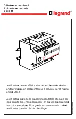
0 038 11
Brand: LEGRAND Pages: 32

HR6S Series
Brand: IDEC Pages: 36

3086FR
Brand: Patton Pages: 170

IBCG51M
Brand: GE Pages: 49

Multilin HID
Brand: GE Pages: 23

CV-21
Brand: ABB Pages: 16

SCR-31-i
Brand: IDEM SAFETY SWITCHES Pages: 4

RNPP-311-1
Brand: Novatek-electro Pages: 4

RECA/E4
Brand: Dossena Pages: 4

DER3B-DUAL Series
Brand: Dossena Pages: 4

6-582
Brand: Modine Manufacturing Pages: 3

X48DS
Brand: FRER Pages: 2

X48DSA Series
Brand: FRER Pages: 2

CL-DR-RL8X8A-N
Brand: Climax Pages: 2


