background image

E32.0.02.6C-04 

Manual for connection and operation of the 

GIA 2000 / AAG and GIR 2002 / AAG

  page 10 of 30

4. Configuration of the measuring input

General description and notes to the operating of the menu

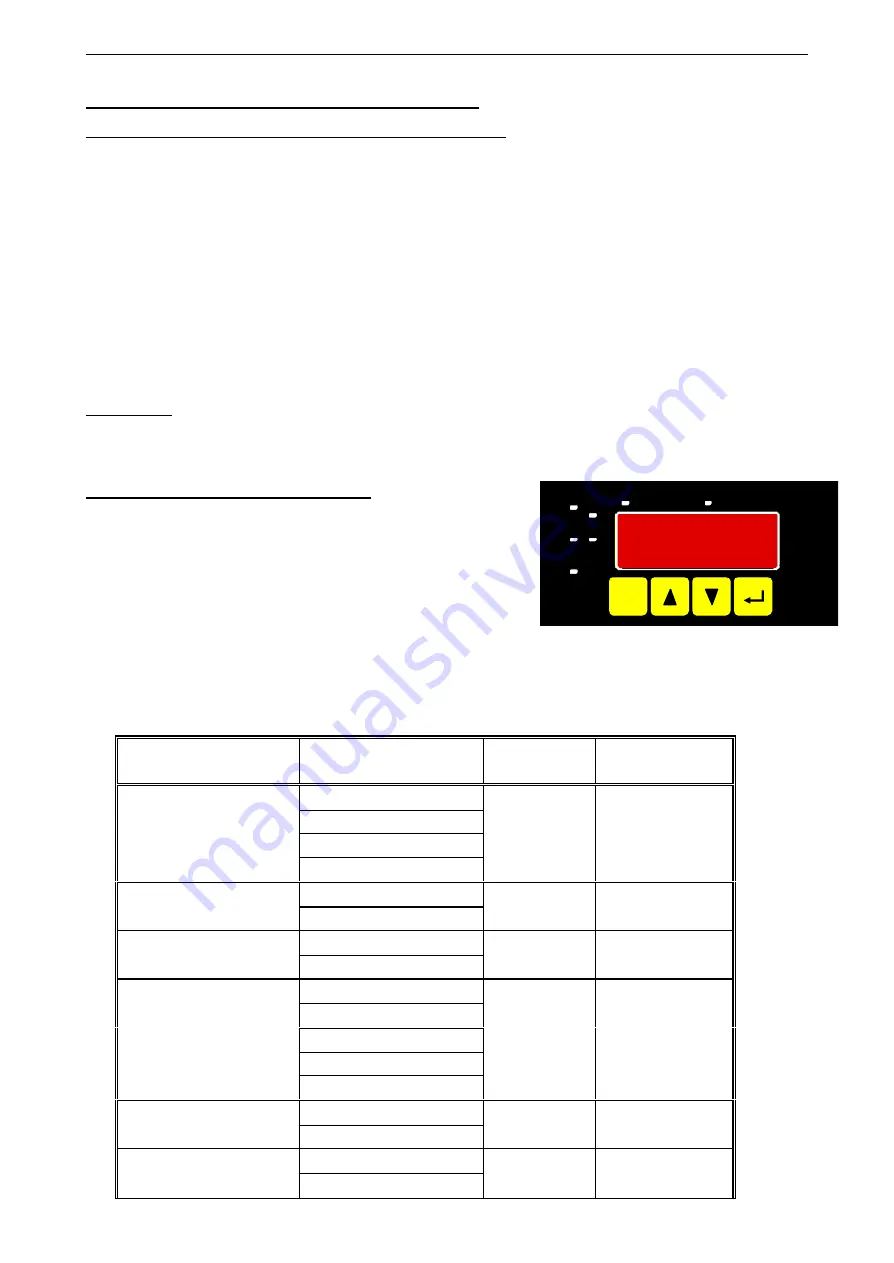
By means of 

button 1 

you can go to the next parameter.

Additionally a given changing in the parameter setting can be confirmed by this button  and the new value
will be saved. Afterwards it will be changed to the parameter view again.

By means of 

button 2

 and 

you can go from the parameter view to the parameter setting and adjust its

value there.

Hint:

The buttons 2 and 3 are featured with a ‘roll-function‘. When pressing the button once the value will be raised
(button 2) by one or lowered (button 3) by one. When holding the button pressed for longer than 1 sec. the value
starts counting up or down, the counting speed will be raised after a short period of time.
The device also features a ‘overflow-function‘, when reaching the upper limit of the range, the device switches to
the lower limit, vice versa.

By means of 

button 4 

a


given changing will be cancelled in the parameter setting. The changing will be dis-

carded and the former parameter value will be preserved.
In the parameter view button 4 closes the menu.

Please note:

  If you don’t press any button for more than 10 sec. in the parameter setting, the adjustment will

be cancelled, the changing discarded and it will be changed to the parameter view. If you don’t
press any button for more than 60 sec. in the menu, the menu will be automatically closed.

4.1. Selecting an input signal type

-

Turn the device on and wait until it completed its built-in seg-
ment test.

-

At the same time press the pushbutton on the rear side (but-
ton 5) and button 2 for >2 seconds.
The device displays “

InP

“ ('INPUT').

-

Use button 2 or button 3 to select the input signal
(see table below).

-

Validate the selection with button 1. The display will show “

InP

“ again.

Depending on the selected input signal, additional configurations will be needed.

Input type

Signal

to select as

input

proceed in chapter

0 – 10 V

0 – 2 V

0 – 1 V

Voltage signal

0 – 50 mV

U

4.2

4 – 20 mA

Current signal

0 – 20 mA

I

4.2

Pt100

RTD

Pt1000

t.rES

4.3

NiCr-Ni

(type K)

Pt10Rh-Pt

(type S)

NiCrSi-NiSi

(type N)

Fe-CuNi

(type J)

Thermocouples

Cu-CuNi

(type T)

t.tc

4.3

TTL-signal

Frequency

Switch-contact NPN, PNP

FrEq

4.4

TTL-signal

Rotation

Switch-contact NPN, PNP

rPn

4.5

ON/SP

SET

min.

OFF/Hy.

1

2

max.

ALARM

Scale

Analog

CAL

Scale

Analog

CAL

ON/SP

SET

min.

OFF/Hy.

1

2

max.

GIR/GIA

ALARM

SET

1

2

3

4

Summary of Contents for GIA 2000

Page 1: ...0 AAG and GIR 2002 AAG page 1 of 30 Manual for connection and operation of GIA 2000 GIR 2002 with option AAG as of version 1 3 GREISINGER electronic GmbH D 93128 Regenstauf Hans Sachs Stra e 26 Phone...

Page 2: ...0 4 1 Selecting an input signal type 10 4 2 Measuring voltage and current 0 50mV 0 1V 0 2V 0 10V 0 20mA 4 20mA 11 4 3 Measuring temperature Pt100 Pt1000 RTD probes and thermocouple type J K N S or T 1...

Page 3: ...tials 5 The device must be switched off and must be marked against using again in case of obvious malfunc tions of the device which are e g visible damage no prescripted working of the device storing...

Page 4: ...IR 2002 has been subjected to various inspection tests and is completely calibrated Before the GIA 2000 or GIR 2002 can be used it has to be configured for the cus tomer s application Important At the...

Page 5: ...e corresponding designation on the label on the housing 2 not available at GIA 2000 3 2 Connection data typical limitations between terminals min max min max notes Supply voltage 1 and 2 207 VAC 244 V...

Page 6: ...ply with separate transmitter supply 3 3 3 Connecting a 0 4 20mA transmitter in 3 wire technology with in device integrated transmitter supply with separate transmitter supply 3 3 4 Connecting a 0 1V...

Page 7: ...uring signal source needs the connection of an external resistor e g the pull up voltage of 3 3V is not enough for the signal source or you want to measure in the top level frequency range In this cas...

Page 8: ...of a sensor signal for a counter signal is the same used for the frequency and rotation signal Please use the wiring diagram given in chapter 3 3 6 There is the possibility to reset the counter When...

Page 9: ...eme care when switching inductive loads like coils or relays etc Because of their high voltage peaks protec tive measures e g RC element to limit these peaks have to be taken Note In case of configuri...

Page 10: ...r parameter value will be preserved In the parameter view button 4 closes the menu Please note If you don t press any button for more than 10 sec in the parameter setting the adjustment will be cancel...

Page 11: ...current 0 50mV 0 1V 0 2V 0 10V 0 20mA 4 20mA This chapter describes how you configure the device for measuring voltage or current signals from an ex ternal transmitter This instruction demands that y...

Page 12: ...ling or exceeding the device will display 0 or 100 Note When exceeding the measuring limit upper measuring range 10 independently from the limit setting the device will always display the correspondin...

Page 13: ...C 274 1742 F J Fe CuNi Type J Meas range 70 0 300 0 C 94 0 572 0 F Meas range 270 400 C 454 752 F t Cu CuNi Type T Meas range 70 0 200 0 C 94 0 392 0 F Validate the selected input signal by pressing...

Page 14: ...button 1 to validate your selection The display shows Fr Lo again When pressing button 1 again the display will show Fr Hi frequency high upper frequency range limit Use button 2 or button 3 to selec...

Page 15: ...pter 4 1 The device has to display InP When pressing button 1 the device will display SEnS Use button 2 or button 3 to select the desired input signal Display Input signal Notes ttL TTL signal nPn Swi...

Page 16: ...the device as a counter This instruction demands that you selected Co up or Co dn as your desired input type like it is explained in chapter 4 1 The device has to display InP When pressing button 1 t...

Page 17: ...ill be displaying dP decimal point Use button 2 or button 3 to select the desired decimal point position Press button 1 to validate your selected decimal point position The display shows dP again Pres...

Page 18: ...s chapter describes how to configure the device as an EASY BUS display This instruction demands that you selected SEri as your desired input type like it is explained in chapter 4 1 The device has to...

Page 19: ...te If you don t press any button for more than 10 sec in the parameter setting the adjustment will be cancelled the changing discarded and it will be changed to the parameter view If you don t press a...

Page 20: ...also features a overflow function when reaching the upper limit of the range the device switches to the lower limit vice versa By means of button 4 a given changing will be cancelled in the parameter...

Page 21: ...1 to validate the selection The display shows 1 Err again When pressing button 1 again the display shows outP output again Now you have finished the output configuration Press now button 4 to exit the...

Page 22: ...red button 3 by one When holding the button pressed for longer than 1 sec the value starts counting up or down the counting speed will be raised after a short period of time The device also features a...

Page 23: ...min max alarm monitoring This instruction demands that you selected AL F1 as your desired output function like it is explained in chapter 6 1 Press button 1 if not already done The device will be dis...

Page 24: ...es the menu Please note If you don t press any button for more than 10 sec in the parameter setting the adjustment will be cancelled the changing discarded and it will be changed to the parameter view...

Page 25: ...est performance data is saved Calling of the minimum value press button 3 shortly the device will display Lo briefly after that the min value is displayed for about 2 sec Calling of the maximum value...

Page 26: ...d Pt1000 Sensor shorted 0 4 20mA Counter overflow Remedies The error message will be reset if the input signal is within the limits check sensor transducer or transmitter check device configuration e...

Page 27: ...tive device Err 9 Sensor defective The device features an integrated diagnostic function for the connected sensor or transmitter When detecting a failure error message Err 9 will be displayed Possible...

Page 28: ...148 0 572 0 F 0 1 C F NiCrSi NiSi Type N 270 1350 C 454 2462 F 1 C F 70 0 300 0 C 94 0 572 0 F 0 1 C F Fe CuNi Type J 170 950 C 274 1742 F 1 C F 70 0 200 0 C 94 0 392 0 F 0 1 C F Thermocouple probes...

Page 29: ...e over contact breaking capacity 10A ohmic load 250 VAC Response Time 25 msec for standard signals 0 5 sec for temperature frequency f 4 Hz Output functions 2 point min max alarm Switching points arbi...

Page 30: ...n is calculated relatively to the tare value Setting the tare function press key 4 shortly the display value will be set to 0 Clearing the tare function press key 4 for 4 seconds the current measuring...

Reviews: