13
30°
45°
Montagehinweise
Assembly instructions
Istruzioni di montaggio
Instructions de montage
Instrucciones de montaje
EN
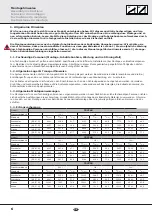
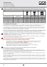
2. Installation Guidelines
2.1. System Alignment
For the installation of the Thermosiphon System, you will need a suitable location without shadow (e.g. no trees, buildings)
throughout the year.
The optimum function of the Thermosiphon System will be obtained if the system is installed pointing South in the Northern Hem-
isphere, as far as possible, and pointing North in the Southern Hemisphere, as far as possible.
The Thermosiphon System is suitable for a minimum inclination between 15 º and a maximum inclination of 45 º. Deviations
from the above panel inclinations are not permitted! The Thermosiphon System may only be exposed to direct sunlight if the
FORVHGZDWHUFLUFXLWLV¿OOHGDQGZDWHUGLVFKDUJHGLVVHFXUHG7KHIURQWRIWKHVRODUSDQHOPXVWRWKHUZLVHEHSURWHFWHGIURPGLUHFW
sunlight.
2.2. Structural engineering aspects
7KHV\VWHPPD\RQO\EHLQVWDOOHGRQDURRIVXUIDFHRUVXEVWUXFWXUHZLWKVXI¿FLHQWORDGEHDULQJFDSDFLW\7KHVWDWLFORDGEHDULQJFDSDFLW\
of the roof or substructure must be checked for compliance with local and regional stipulations at the site prior to the installation of the
Thermosiphon system, if necessary by means of the commissioning of a structural engineer (see also the weight data). In particular, it is
LPSRUWDQWWRFKHFNZKHWKHUWKHTXDOLW\RIWKHZRRGHQVXEVWUXFWXUHLVVXI¿FLHQWWRHQVXUHORQJODVWLQJVFUHZFRQQHFWLRQVIRUIDVWHQLQJ
WKH7KHUPRVLSKRQ6\VWHP7KHRQVLWHFKHFNLQJRIWKH7KHUPRVLSKRQ6\VWHPDVSHU(1RUWKHFRXQWU\VSHFL¿FUHTXLUHPHQWVLVSDU
ticularly important in areas prone to heavy snow or high wind speeds. When doing this, you need also to investigate all the peculiarities of
the erection location (prevailing winds, venturi effects, eddies, etc.) that may lead to locally increased loading.
2.3. Information Regarding Inclined Roofs
7KHLQVWDOODWLRQRIDFROOHFWRU¿HOGLVDQLQWHUYHQWLRQLQDQH[LVWLQJURRI5RRIFODGGLQJVXFKDVWLOHVVKLQJOHDQGVODWHDWWLFVZLWK
a special construction or that are used for residential purposes, and roof pitches that are below the minimum recommended value
require (in relation to the cladding) additional measures to be carried out by the customer in order to protect against the penetra-
tion of water as a result of wind force and driving snow. This might include sub-roof membranes, for example. To prevent over-
ORDGLQJWKHURRIFODGGLQJMRLQWVIRUKDQJHUVFUHZVDPHWDOURR¿QJWLOHPXVWEHXVHGIURPDFKDUDFWHULVWLFVQRZORDG6N!
kN/m². When selecting the installation site, note that the maximum permitted loads must not be exceeded as a result of snow or
ZLQGIRUFHV$VDJHQHUDOUXOHFROOHFWRU¿HOGVPXVWEHLQVWDOOHGLQDZD\WKDWDOORZVVQRZWRVOLGHIUHHO\RIIWKHFRQQHFWRUV$Q\
EXLOGXSRIVQRZFDXVHGE\VQRZFDWFKHUPHVKRUE\VSHFL¿FHUHFWLRQVLWXDWLRQVPXVWQRWUHDFKWKHVRODUSDQHOV6QRZFDWFKHUV
must be installed 0.5 m above the top of the panels to ensure that the panels themselves do not act as snow catchers. To prevent
inadmissible wind loads, the collectors may not be installed at the edge of a roof (e/10 edge zones as per EN1991, but with a
minimum gap of 1 m). In particular, in the case of elevated structures, the top of a panel must not protrude above the roof ridge.
Panels must not be installed below a height transition so that it is not possible for excess loads to fall onto the panel system from
the higher level as a result of drifting or sliding snow. If, to solve this problem, snow catchers are installed at the higher level, the
statics of this roof must also be checked.
2.4. Information Regarding Flat Roofs
The installation of a Thermosiphon System is an intervention in an (existing) roof. Attics with a special construction or that are used for
residential purposes and roof pitches that are below the minimum recommended value require (in relation to the cladding) additional
measures to be carried out by the customer in order to protect against the penetration of water as a result of wind force and driving
snow. This might include sub-roof membranes, for example. When selecting the installation site, note that the maximum permitted loads
must not be exceeded as a result of snow or wind forces. To prevent inadmissible wind loads, the Thermosiphon System must not be
installed at the edge of a roof (e/10 edge zones as per EN 1991, but minimum gap of 1 m). The Thermosiphon System must not be in-
stalled below a height transition so that it is not possible for excess loads to fall onto the Thermosiphon System from the higher level as a
result of drifting or sliding snow. If, to solve this problem, snow catchers are installed at the higher level, the statics of this roof must also
be checked. In the case of larger Thermosiphon System installations (several connected in parallel), we recommend that you mount each
V\VWHPRQLWVRZQVHSDUDWHEHDULQJVWUXFWXUHPDGHIURPVWHHOSUR¿OHV$WWDFKPHQWXVLQJFRQFUHWHEDOODVWEORFNVHQDEOHVWKHV\VWHPWR
be installed without penetrating the roof cladding. If the systems are mounted on concrete ballast blocks, rubber underlays must be used
to increase the static friction between the concrete ballast blocks, thus preventing damage to the roof cladding.
2.5. Lightning protection
$VSHUWKHVWLSXODWLRQVRI/LJKWQLQJ3URWHFWLRQ6WDQGDUG(13DUWVWKHFROOHFWRU¿HOGPXVWQRWEHFRQQHFWHGWRWKH
EXLOGLQJVOLJKWQLQJSURWHFWLRQ%H\RQGWKHVFRSHRIYDOLGLW\RIWKLVVWDQGDUGFRXQWU\VSHFL¿FUHTXLUHPHQWVPXVWEHREVHUYHG$
safety gap of at least 1 m from any adjacent conductive object is to be maintained. In the case of installations on top of existing
PHWDOVXEVWUXFWXUHVDQDXWKRULVHGDQGTXDOL¿HGHOHFWULFLDQPXVWJHQHUDOO\EHFRQVXOWHG7RHQDEOHHTXLSRWHQWLDOERQGLQJRIWKH
EXLOGLQJWKHPHWDOOLFFRQGXFWRUSLSHVRIWKHVRODUFLUFXLWDQGDOORIWKHSDQHOKRXVLQJ¿[WXUHVPXVWEHFRQQHFWHGWRWKHPDLQ
HTXLSRWHQWLDOEXVEDULQDFFRUGDQFHZLWK(1DQGRUFRXQWU\VSHFL¿FUHTXLUHPHQWVE\DQDXWKRULVHGDQGTXDOL¿HGHOHFWUL
cian.
3. Operational Recommendations
3.1. Frost Protection
In frost-endangered areas, the Thermosiphon System must be protected from frost. This can be achieved by using an electric im-
mersion heater in the process water circuit. The storage tank in the Thermosiphon System is already prepared for its installation
DVVWDQGDUG$QDSSURSULDWHHOHFWULFLPPHUVLRQKHDWHULVDYDLODEOHDVDUHWUR¿WNLW7KHVRODUFLUFXLWLVSURWHFWHGIURPIUHH]LQJE\
the use of an antifreeze-water mixture (see also "Flushing and Filling").
Summary of Contents for TSC160
Page 1: ...DE Handbuch EN I F E Manual Manuale Manuel Manual 30 45 160 200 300...
Page 2: ......
Page 73: ...73 30 45 DE EN IT FR ES Notizen Notice Appunti Notes Notas...
Page 74: ...74 30 45 DE EN IT FR ES Notizen Notice Appunti Notes Notas...
Page 75: ......
Page 76: ......


