GRASS VALLEY M-122A User Manual Download Page 115

20 April 2005

M-Series User Manual

115

Adjusting video output

2. Make your video output adjustments or select 

Default

 to return all video output 

settings to their factory default values. See also 

“Setting record channel NTSC 

pedestal” on page 108

 for related record channel settings. 

These composite analog video output settings are active and can be monitored on 
the video output without closing the Configuration dialog box.

3. Change other settings as necessary in the Configuration dialog box, then select 

OK


to save and apply all changes at once.

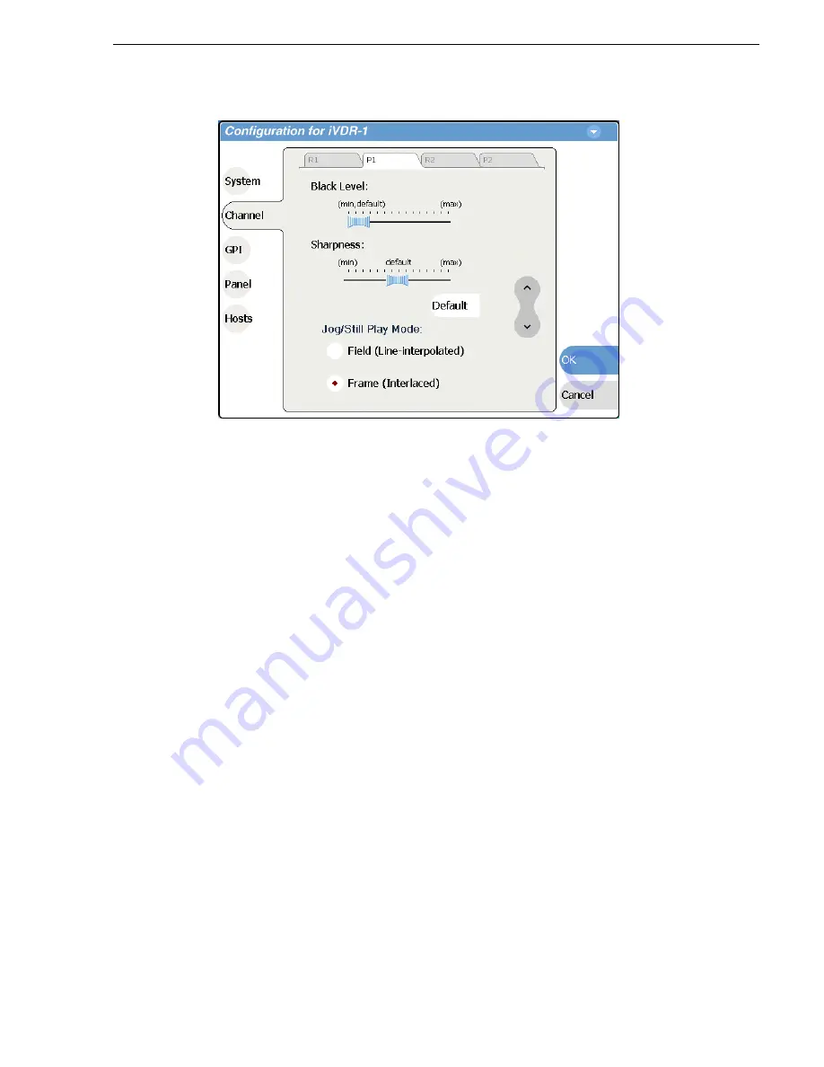
Selecting the Jog/Still-Play mode setting

Jog/Still-Play mode settings determine how to generate the still-play signal for the 
play channel when it is setup to freeze on last frame of video in stop mode. You can 
select line interpolated, or interlaced. Note that in normal play mode, the play channel 
can be setup for E to E mode instead of displaying freeze frame in stop mode. E to E 
mode is enabled/disabled in the application running on the channel. Refer to the 

“Guide to using Player: Play View” on page 160

, or 

“Guide to using Playlist: List 

View” on page 188

.

1. Select 

System

 and choose 

Configuration

, then select the 

Channel

 button, select the 

P1 

or 

P2

 tab, and open the 

Video Output

 link. Close other links or use the scroll 

button if necessary to locate the link.

2. Locate the still play mode settings.

Summary of Contents for M-122A

Page 1: ...M Series INTELLIGENT VIDEO DIGITAL RECORDER User Manual SOFTWARE VERSION 2 0 071 8327 01 APRIL 2005 the most watched worldwide ...

Page 2: ...duct options and specifications subject to change without notice The information in this manual is furnished for informational use only is subject to change without notice and should not be construed as a commitment by Thomson Broadcast and Media Solutions Inc Thomson Broadcast and Media Solutions Inc assumes no responsibility or liability for any errors or inaccuracies that may appear in this pub...

Page 3: ...ect system settings 32 Select the video input 34 Select the audio input digital models only 35 Select timecode source 36 Verifying basic operation 36 Setting up the Ethernet network 37 Connecting the Ethernet network cabling 37 100BaseT Configuration Data and streaming between iVDRs 38 1GBaseT Configuration Data and streaming between iVDRs 42 Operating with both 100BT and 1GBT network connections ...

Page 4: ...s 91 Writing data to the CD R RW and DVD drives 93 Formatting CD R RW and DVD disks 93 Reading CD ROMs and DVDs in other iVDRs or computers 95 Chapter 4 Modifying Configuration Using Configuration Manager 98 Opening and closing Configuration Manager 99 Saving and restoring custom iVDR configuration 100 Restoring default settings 101 Selecting the video standard 102 Setting the audio reference leve...

Page 5: ...ecord mode 148 Changing video compression settings 151 Selecting the audio monitor source 151 Changing the timecode source 152 Changing the current bin 154 Previewing a clip 154 Renaming a clip 155 Viewing clip properties 155 Locating a clip 156 Displaying available storage space 156 Chapter 7 Playing and Editing Before using Player 158 Working with clips that are still recording 158 Monitoring th...

Page 6: ...etting monitor information 195 Creating a list 196 Opening an existing list 196 Renaming a list 196 Inserting play events 196 Selecting the insertion point 196 Inserting play events in List view 197 Inserting play events in Event view 197 Using copy and paste to insert play events 198 Inserting a clip that is still recording 199 Inserting a playlist in a playlist 199 Using GPI output triggers in p...

Page 7: ...231 Deleting a bin 232 Renaming a bin 233 Working with assets 234 Renaming an asset 234 Selecting multiple assets 234 Moving an asset to another bin 235 Copying an asset 236 Deleting an asset 239 Erasing a clip s unused media 239 Locking an asset 241 Working with the Recycle Bin 242 Viewing the Recycle Bin contents 242 Emptying the Recycle Bin 242 Bypassing the Recycle Bin when deleting 242 Locati...

Page 8: ...Recorder Local Protocol mode 285 Guide to Protocol Player Protocol Only mode 288 Guide to Protocol Player Local Protocol mode 290 Using Protocol Recorder Local control tasks 293 Using Protocol Player Local control tasks 293 Playout using current and preview clips 293 Skipping to the preview clip during playout 295 Jumping to a specific timecode 295 Monitoring remote control communications 297 Appe...

Page 9: ...9 Rack mount hardware shipped with the iVDR 310 Mounting the Rack Slides 311 Installing the iVDR on the rack mount rails 313 Making Rack Slide Adjustments 313 Adjusting rack mount brackets 314 Rear panel connector pin outs 315 RS 422 connector pinouts 315 LTC connectors pinouts 315 Analog audio connector pinouts 316 GPI I O connector pinouts 316 Index 317 ...

Page 10: ...10 M Series User Manual 20 April 2005 Contents ...

Page 11: ...DR configuration settings using the Configuration dialog box Chapter 5 Using the Monitor Pane Provides information for using the Monitor pane and for customizing it to suit your workflow Chapter 6 Recording Clips Describes how to use the Recorder application to record clips Chapter 7 Playing and Editing Describes how to use the Player application to play clips trim clips and create subclips Chapte...

Page 12: ...including recording and playing clips trimming clips and making a playlist M Series iVDR Release Notes Contains the latest information about the M Series iVDR software shipped on your system The information in this document includes software upgrade instructions software specifications and requirements feature changes from the previous releases and any known problems M Series iVDR Service Manual C...

Page 13: ...u The M Series Help home page is displayed or In any M Series application or tool select the context menu then choose Help Online help for the application is displayed Printed manuals in PDF format All printed manuals are available in the Acrobat file format pdf on the M Series iVDR System Software CD ROM The manuals are located in the CD ROM Documentation directory Thomson Grass Valley Web site T...

Page 14: ...rt is available for warranty and contract customers Authorized Support Representative A local authorized support representative may be available in your country To locate the support representative for your country visit the product support Web page on the Grass Valley Web site United States 800 547 8949 Toll Free France 33 1 34 20 77 77 Latin America 800 547 8949 Toll Free Germany 49 6155 870 606...

Page 15: ...nected to earth ground Before making connections to the input or output terminals of the product ensure that the product is properly grounded Do Not Operate Without Covers To avoid electric shock or fire hazard do not operate this product with covers or panels removed Do Not operate in Wet Damp Conditions To avoid electric shock do not operate this product in wet or damp conditions Do Not Operate ...

Page 16: ...ult in personal injury or loss of life CAUTION Caution statements identify conditions or practices that may result in damage to equipment or other property or which may cause equipment crucial to your business environment to become temporarily non operational Terms on the Product These terms may appear on the product DANGER indicates a personal injury hazard immediately accessible as one reads the...

Page 17: ... Certifications and Compliances Canadian Certified Power Cords Canadian approval includes the products and power cords appropriate for use in the North America power network All other power cords supplied are approved for the country of use FCC Emission Control This equipment has been tested and found to comply with the limits for a Class A digital device pursuant to Part 15 of the FCC Rules These...

Page 18: ...including interference that may cause undesirable operation Laser Compliance Laser Safety Requirements The device used in this product is a Class 1 certified laser product Operating this product outside specifications or altering its original design may result in hazardous radiation exposure and may be considered an act of modifying or new manufacturing of a laser product under U S regulations con...

Page 19: ...pliance with ANSI UL60950 CAN CSA C22 2 No 60950 00 12 01 2000 Safety of Information Technology Equipment including Electrical Business Equipment Third edition IEC 950 Safety of Information Technology Equipment including Electrical Business Equipment Third edition 1999 EN60950 Safety of Information Technology Equipment including Electrical Business Equipment Third Edition 2000 ...

Page 20: ...20 M Series User Manual 20 April 2005 Safety Summaries ...

Page 21: ... Procedures in this chapter include Making connections for basic operation VGA Display hot key sequence Powering on and shutting down Configuring for basic operation Verifying basic operation Setting up the Ethernet network Connecting IEEE 1394A Connecting RS422 Connecting GPI ...

Page 22: ...u s h P u s h Cmpst REF R1 IN P1 OUT P1 OUT Composite R1 P1 R2 IN P2 OUT P2 OUT Composite R2 P2 R1 IN P1 OUT P1 OUT SDI R1 P1 R2 IN P2 OUT P2 OUT L SDI R2 P2 Loop Thru Audio MON O P1 CH1 R2 CH1 P2 CH2 OUT IN P1 LTC P1 CH2 P2 LTC P2 CH1 R1 LTC R2 CH2 R2 LTC R1 CH2 R1 CH1 Analog Audio Analog Audio P u s h P u s h P u s h P u s h P u s h P u s h Cmpst REF R1 IN P1 OUT P1 OUT Composite R1 P1 R2 IN P2 ...

Page 23: ...UT P1 OUT SDI R1 P1 R2 IN P2 OUT P2 OUT L SDI R2 P2 Loop Thru Audio MON O P1 CH1 R2 CH1 P2 CH2 OUT IN P1 LTC P1 CH2 P2 LTC P2 CH1 R1 LTC R2 CH2 R2 LTC R1 CH2 R1 CH1 Analog Audio Analog Audio P u s h P u s h P u s h P u s h P u s h P u s h Cmpst REF R1 IN P1 OUT P1 OUT Composite R1 P1 R2 IN P2 OUT P2 OUT Composite R2 P2 R1 IN P1 OUT P1 OUT SDI R1 P1 R2 IN P2 OUT P2 OUT L SDI R2 P2 Loop Thru Audio M...

Page 24: ...1 OUT AUD MON OUT PORT 1 PORT 2 RS422 SCSI VGA FRONT PANEL Digital Audio Recorder 1 Inputs R1 Composite SDI Video P1 CH1 R2 CH1 P2 CH2 OUT IN P1 LTC P1 CH2 P2 LTC P2 CH1 R1 LTC R2 CH2 R2 LTC R1 CH2 R1 CH1 Analog Audio Analog Audio P u s h P u s h P u s h P u s h P u s h P u s h R1 IN R1 IN CH 1 2 CH 1 2 CH 3 4 CH 3 4 P1 OUT P1 OUT 1 L R P1 OUT 2 R2 IN R2 IN CH 1 2 CH 1 2 CH 3 4 CH 3 4 P2 OUT P2 OU...

Page 25: ...P1 OUT AUD MON OUT PORT 1 PORT 2 RS422 SCSI VGA FRONT PANEL Digital Audio Player 1 Outputs P1 Composite SDI Video P1 CH1 R2 CH1 P2 CH2 OUT IN P1 LTC P1 CH2 P2 LTC P2 CH1 R1 LTC R2 CH2 R2 LTC R1 CH2 R1 CH1 Analog Audio Analog Audio P u s h P u s h P u s h P u s h P u s h P u s h R1 IN R1 IN CH 1 2 CH 1 2 CH 3 4 CH 3 4 P1 OUT P1 OUT 1 L R P1 OUT 2 R2 IN R2 IN CH 1 2 CH 1 2 CH 3 4 CH 3 4 P2 OUT P2 OU...

Page 26: ...tions on a larger screen size however you must first enable the VGA output Refer to Enabling the VGA monitor output on page 86 NOTE You can use the USB connectors provided along the edge of the optional Front Panel to connect a keyboard or mouse P1 CH1 R2 CH1 P2 CH2 OUT IN P1 LTC P1 CH2 P2 LTC P2 CH1 R1 LTC R2 CH2 R2 LTC R1 CH2 R1 CH1 Analog Audio Analog Audio P u s h P u s h P u s h P u s h P u s...

Page 27: ...s h P u s h P u s h P u s h P u s h 4 L R R2 IN R2 IN CH 1 2 CH 1 2 CH 3 4 CH 3 4 P2 OUT P2 OUT 1 P2 OUT 2 CMPST R2 P2 SDI R2 P2 AES EBU R2 P2 REF COMPOSITE LOOP THRU R2 IN P2 OUT AUD MON OUT GPI PORT 3 PORT 4 1394 RS422 PORT 1 PORT 2 RS422 SCSI VGA FRONT PANEL Left Ch1 Right Ch2 CH1 P2 CH2 OUT IN P2 CH1 R2 CH2 Analog Audio P u s h L R ru GPIO Audio MON Out Left Ch1 Right Ch2 PORT 3 PORT 4 RS422 P...

Page 28: ...dio P u s h P u s h P u s h P u s h P u s h L R R2 IN R2 IN CH 1 2 CH 1 2 CH 3 4 CH 3 4 P2 OUT P2 OUT 1 P2 OUT 2 CMPST R2 P2 SDI R2 P2 AES EBU R2 P2 REF COMPOSITE LOOP THRU R2 IN P2 OUT AUD MON OUT GPI PORT 3 PORT 4 1394 RS422 PORT 1 PORT 2 RS422 SCSI VGA FRONT PANEL M 222D M322D Reference in out OR Reference in out R2 CH1 P2 CH2 OUT IN P2 LTC P2 CH1 R2 CH2 R2 LTC Analog Audio P u s h P u s h P u ...

Page 29: ...TRL ALT C hot key sequence when AppCenter is fully initialized after power up to switch the display adapter card to 800x600 display settings If you inadvertently select this key sequence on an iVDR with a front panel press the CTRL ALT L hot key sequence to return to 640x480 display settings which is required for front panel operation P1 LT R1 LTC P u s h R1 IN P1 OUT P1 OUT Composite R1 P1 R2 IN ...

Page 30: ...o shutdown or restart 1 In the AppCenter toolbar select System then choose Shutdown in the pop up menu The Shutdown dialog box appears 2 In the Shutdown dialog box choose a shutdown mode using the drop down list then select OK Unlatch and lower the drive bay door L Push the standby switch Wait for the Windows operating system to startup then the iVDR applications start automatically 1 2 ...

Page 31: ...m must be disconnected from the power source Shutdown Mode Description Exit to Windows Exit AppCenter and display the Windows desktop Use the desktop shortcut to restart AppCenter Restart Exit AppCenter and restart the Windows operating system AppCenter will restart automatically Storage Maintenance Mode Exit AppCenter and restart the iVDR in storage maintenance mode to allow maintenance on the me...

Page 32: ... operating system settings unless approved by Grass Valley including but not limited to the following Do not use the User Manager Do not use the Disk Administrator Do not load any third party software Do not install any Windows updates other than critical updates without contacting Grass Valley Product Support Configuring for basic operation Use the following procedures to configure the iVDR for b...

Page 33: ...et the audio reference level for the iVDR 5 Scroll down to locate the question What is your channel compression type 6 Select one of the following compression types DV25 or DV50 When you make these selections no further compression settings are available or necessary Select OK to save this setting and when prompted restart the iVDR Restarting is required for the video compression changes to take e...

Page 34: ...inserted in the vertical blanking interval VBI Otherwise you should select Active picture only option The VBI information is compressed along with the picture content You may need to increase the data rate if you have trouble with the integrity of the VBI signals during playback 10 Select OK to save all changes at once 11 When prompted restart the iVDR The restart is required to put the video comp...

Page 35: ...his selection to record SDI component video connected to the record channel s SDI input If a warning message is displayed about SDI not present verify that and SDI signal is connected 5 Select OK to save changes or proceed to Select the audio input digital models only Select the audio input digital models only You must select the audio input on iVDR models equipped with digital audio inputs To sel...

Page 36: ... when no signal is detected for the audio input you select NOTE Audio is output simultaneously on all audio outputs When using embedded audio you must ensure that the correct embedded audio group is selected for each play channel You can disable embedded audio output if needed See Configuring SDI output embedded audio on page 120 Select timecode source The timecode source for each record channel i...

Page 37: ...standard data network capability and for streaming media transfers between iVDRs Operating with both 100BT and 1GBT network connections Describes how to set up both networks so that you can use the low speed network for standard data network tasks and the high speed network for streaming transfers between iVDRs 100BaseT Configuration iVDR and Profile XP streaming Follow these instructions if you u...

Page 38: ...ng on page 39 Configure Windows network settings 1 If you normally operate your M Series iVDR using the optional Front Panel touch screen you should connect keyboard and mouse before proceeding Refer to Keyboard mouse and VGA monitor connections on page 26 for instructions You will likely find it easier to configure your network using a keyboard and mouse rather than the touch screen You may need ...

Page 39: ...asks Add network hosts names for streaming You must add the host names of all peer iVDRs on the network that support streaming transfers Adding host names is required to allow selection of networked iVDRs in the AppCenter user interface and to provide a successful network connection for streaming The host names added will appear in the Import and Send to dialog boxes NOTE By default the iVDR host ...

Page 40: ...esult in being unable to connect to the iVDR b If you are using remote protocols to perform video network transfers you must use the following steps to add a unique Controller ID for each host otherwise you can ignore this step and proceed to step c Select the Enter controller ID text entry control Enter the controller ID of the iVDR then select OK Make sure to enter a number between 1 and 255 tha...

Page 41: ...or streaming operation Refer to Importing assets from another iVDR or Profile XP system on page 260 and Sending assets to another machine on page 265 for procedures on transferring media NOTE If you have trouble try using the ping utility in the Windows command prompt using either the IP address or host name Troubleshoot as needed Also refer to the M Series Service Manual for troubleshooting proce...

Page 42: ...d on the iVDRs All name resolution must be through hosts files located on each networked device The host name of all peer iVDRs must be added to a host registry using the iVDR Configuration tool Procedure summary Set the static IP address Set up hosts files Add network hosts names for streaming Set the static IP address This procedure guides you to relevant settings It is assumed that you understa...

Page 43: ...nnot be set to DNS or WINS You must set up a hosts file located in c winnt system32 drivers etc hosts on each iVDR If you include the names and addresses of all the iVDRs on the network then you can create one file and copy it to all the machines instead of editing the hosts file on each machine On each iVDR set up the hosts files as follows 1 Open the following file using Notepad or some other te...

Page 44: ...oot your machine 5 Copy the new hosts file onto all the other machine to save you editing it again 6 Proceed to Add network hosts names for streaming Add network hosts names for streaming You must add the host names of all peer iVDRs on the network that support streaming transfers Adding host names is required to allow selection of networked iVDRs in the AppCenter user interface and to provide a s...

Page 45: ...sts button The network host names are displayed 4 Select Add to open the Add Host dialog box then do the following a Select the Enter host name text entry control then enter the computer name of a peer iVDR Make sure to enter the exact computer name Any differences will result in being unable to connect to the iVDR b If you are using remote protocols to perform video network transfers you must use...

Page 46: ...tion Data and streaming between iVDRs on page 42 The low speed adapter and high speed adapter are configured independently and each must have its own unique IP address and network setup Dual network adapters can create parallel network paths Parallel network paths occur when the iVDR is networked with other devices with dual network adapters and those devices are connected to the same 100BaseT and...

Page 47: ...is case sensitive In addition Media Manager does not support the iVDR which means you cannot browse media on the iVDR or initiate transfers from Media Manager running on the Profile XP Media Platform All transfers are initiated in the iVDR user interface Setting up the iVDR for streaming transfer with Profile XP Media Platforms has the following network requirements No DHCP and WINS DNS etc Do not...

Page 48: ... with these procedures contact your network administrator To set up the static IP address on the 100BaseT adapter 1 If you normally operate your M Series iVDR using the optional Front Panel touch screen you should connect keyboard and mouse before proceeding You will likely find it easier to configure your network using a keyboard and mouse rather than the touch screen Refer to Keyboard mouse and ...

Page 49: ...nnt system32 drivers etc hosts on each iVDR If you include the names and addresses of all the iVDRs on the network then you can copy the same file onto all these machines instead of editing the hosts file on each machine On each iVDR set up the hosts files as follows 1 Open the following file using Notepad or some other text editor c winnt system32 drivers etc hosts 2 Enter text in a single line f...

Page 50: ...ile proceed to the next procedure Add network hosts names for streaming Add network hosts names for streaming You must add the host names of all peer iVDRs on the network that support streaming transfers Adding host names is required to allow selection of networked iVDRs in the AppCenter user interface and to provide a successful network connection The host names added appear in the Import and Sen...

Page 51: ...ferences will result in being unable to connect to the iVDR b If you are using remote protocol to perform video network transfers you must use the following steps to add a unique Controller ID for each host otherwise you can ignore this step and proceed to step c Select the Enter controller ID text entry control Enter the controller ID of the iVDR or other networked device then select OK Make sure...

Page 52: ...s You must use static IP address and not some automated method of setting IP address such as DHCP Refer to the Profile XP System Guide or the appropriate manual for your non M Series device to setup the network address After configuring the Profile XP IP address proceed to the next procedure Test the network Test the network Refer to Importing assets from another iVDR or Profile XP system on page ...

Page 53: ...VDR that use industry standard serial protocols You can connect up to four RS422 cables to control iVDR channels depending on your remote control needs Connect the RS422 cabling as required then refer to Using Remote Control Protocols on page 277 to configure the iVDR for remote control R2 CH1 P2 CH2 OUT IN P2 LTC P2 CH1 R2 CH2 R2 LTC Analog Audio P u P u s h P u s h Cmpst REF OUT L R Loop Thru GP...

Page 54: ...on a single DB 25 rear panel connector Also see the following related sections of this manual GPI I O connector pinouts on page 316 GPI I O specifications on page 305 Configuring GPI inputs outputs on page 121 Using GPI output triggers in playlists on page 200 T R GPIO Out PORT 3 PORT 4 RS422 PORT 1 PORT 2 RS422 SCSI VGA FRONT PANEL GPI in out ...

Page 55: ...20 April 2005 M Series User Manual 55 Chapter 2 Quick Start Procedures Quick start procedures in this chapter include To record a clip To play a clip To trim a clip To create a playlist ...

Page 56: ...llustrated Alternate controls for keyboard mouse and monitor are marked with an asterisk and are provided on the VGA monitor only VAR JOG SHTL R1 P2 P1 R2 Display split screen view 2 Select Monitor Verify video source 4 5 Adjust audio R1 Choose record channel 1 3 or 1 VAR JOG SHTL R1 P2 P1 R2 6 Begin record 7 Stop record 8 Rename clip 9 or or Load and play the clip as explained in To play a clip ...

Page 57: ...ontrols for keyboard mouse and monitor are marked with an asterisk and are provided on the VGA monitor only VAR JOG SHTL R1 P2 P1 R2 P1 Display split screen view Choose play channel 1 Select Clips Choose a clip Load the clip 3 4 5 6 2 Press latch and adjust front panel viewing angle 1 or or or Rotate Push VAR JOG SHTL R1 P2 P1 R2 Select Monitor Monitor audio with headphones Play the clip 7 8 9 or ...

Page 58: ...ouse and monitor rather than the touch panel as illustrated Alternate controls for keyboard mouse and monitor are marked with an asterisk and are provided on the VGA monitor only VAR JOG SHTL R1 P2 P1 R2 Select Monitor Locate a frame 2 3 Set in or out mark to current timecode 4 or Load a clip into play channel 1 as explained in To play a clip 1 ...

Page 59: ...ather than the touch panel as illustrated Alternate controls for keyboard mouse and monitor are marked with an asterisk and are provided on the VGA monitor only Select Clips 4 VAR JOG SHTL R1 P2 P1 R2 Choose channel P2 2 or P2 VAR JOG SHTL R1 P2 P1 R2 Select Monitor Play the list 1 Select Playlist on P2 3 5 Drag clips to list 6 or Playlist Player Remote AMP ...

Page 60: ...60 M Series User Manual 20 April 2005 Chapter 2 Quick Start Procedures ...

Page 61: ...udes Product overview Determining storage capacity Front view with optional Front Panel Rear panel view Guide to using AppCenter Using Keyboard shortcuts Guide to using the Front Panel Monitoring the system using the StatusBar Using the StatusPane Writing data to the CD R RW and DVD drives on page 93 ...

Page 62: ...ll being recorded and that the a clip can be played simultaneously and independently on multiple channels Optional Front Panel The optional front panel features 640 by 480 TFT display with touch screen and VTR like transport controls The front panel can be tilted to a convenient operating angle or removed and operated as a desktop device using an optional 15 foot extension cable and cradle The use...

Page 63: ...AES EBU Digital Audio 4 ch video Conforms to SMPTE 276M 1995 Available in models M 222D M 322D only Embedded Audio 4ch video user selectable audio group 1 4 Data format conforms to SMPTE 272M 1994 Available in models M 222D M 322D only Timecode LTC 1ch per record channel 1 ch per play channel VITC Lines 10 22 525 Line Lines 6 23 625 Line Reader automatic detection or user selectable line numbers I...

Page 64: ...g standard file formats such as AVI DV and General Exchange Format GXF as described in SMPTE 360M Files can be exchanged over a network connection or common forms of removable media such as CD RW DVD RW optional Remote control support You can use remote control devices and applications software developed for the M Series iVDR that use industry standard serial protocols For each supported protocol ...

Page 65: ... E to E path is provided for monitoring purposes When E to E mode is enabled the play channel video and audio outputs are switched to the corresponding record channel inputs when the play channel is in stop mode or when no clip is loaded The following table describes play channel operation depending the E to E selection E to E Setting Play channel mode Play channel output Disabled Play FF Rewind S...

Page 66: ...n installed A storage option adds three disk drives Storage options available include of 36GB 73GB and 146GB disk drives These storage options can be mixed for example the iVDR can contain the three 36GB disk option with the three 146GB disk option The following tables show the storage capacity estimates based on the number of disk drives installed and the video data rate The estimates in the tabl...

Page 67: ...dard Number of Drives 3 6 18 Mbs 22 hrs 44 hrs 20 Mbs 20 hrs 40 hrs 25 Mbs 16 hrs 32 hrs 50 Mbs 8 hrs 16 hrs Video Data Ratea a Calculated using 1 video track 4 audio tracks 1 timecode track and the 525 video standard Number of Drives 3 6 18 Mbs 43 hrs 86 hrs 20 Mbs 39 hrs 79 hrs 25 Mbs 32 hrs 65 hrs 50 Mbs 17 hrs 34 hrs Video Data Ratea a Calculated using 1 video track 4 audio tracks 1 timecode t...

Page 68: ... illustrations show the front view of the M Series iVDR with the optional Front Panel installed VAR JOG SHTL R1 P2 P1 R2 Optional Front Panel Drive Bay Door VAR JOG SHTL R1 P2 P1 R2 Push the latch to lower the door Drive Bay Door Lowered and In Open Position Standby Switch Optional DVD RW Drive CD RW Drive Floppy Drive ...

Page 69: ...BU R1 P1 CMPST R2 P2 SDI R2 P2 AES EBU R2 P2 REF COMPOSITE LOOP THRU R2 IN P2 OUT R1 IN P1 OUT AUD MON OUT GPI PORT 3 PORT 4 RS422 PORT 1 PORT 2 RS422 SCSI VGA FRONT PANEL M 222D M322D P1 CH1 R2 CH1 P2 CH2 OUT IN P1 LTC P1 CH2 P2 LTC P2 CH1 R1 LTC R2 CH2 R2 LTC R1 CH2 R1 CH1 Analog Audio Analog Audio P u s h P u s h P u s h P u s h P u s h P u s h Cmpst REF R1 IN P1 OUT P1 OUT Composite R1 P1 R2 I...

Page 70: ...ecorder application that provides a single interface for tasks such as configuration clip management media transfers channel monitoring system monitoring and record and playback control Starting AppCenter There are two ways of restarting AppCenter At power up the Windows operating system starts automatically logs on using the mseries user account password mseries and then automatically launches Ap...

Page 71: ...ntrol the iVDR through keyboard shortcuts Remote Control GPI I O GPI input triggers can be assigned to channels to control actions such as record play stop and skip a playlist event GPI output triggers can be defined for channels and inserted in playlists to control external equipment as the list is played See Configuring GPI inputs outputs on page 121 Serial Control Protocols over RS 422 The iVDR...

Page 72: ...bar Contains the buttons used to control AppCenter Channel Select Tabs Used to select the active channel The active channel receives input from the touch screen front panel controls or mouse and keyboard Transport Controls Used to control record and playback Transport controls do not appear when the front panel is used StatusBar Displays status and error messages and includes tool buttons for open...

Page 73: ...switched to follow the video channel monitored Displays the media management application in the Tools pane which allows you to manage media stored on the iVDR move delete copy import export Application View Buttons View buttons appear in the AppCenter toolbar for channel applications that have more than one view The view buttons for Playlist are shown here Opens the edit pop up menu which includes...

Page 74: ...e Channel Type Required Essentials Tasks Recorder Recorder Recording clips Player Control View Cue View Player Play clips edit and trim clips create sub clips and playout using cue points Protocol Applications including Player and Recorders Player Operate remotely using industry standard serial control protocols over RS 422 or Ethernet Protocol specific recorderandplayerapplications are provided f...

Page 75: ... in the media file system including view properties move copy delete transfer and import export Monitor Pane Monitoring channel input or output and selecting channel control applications Configuration Manager Configuring system settings Transfer Monitor Monitoring media transfers including network transfers and file import export Shutdown Dialog Box Power off or restart the iVDR Online Help Select...

Page 76: ...e button At the end of the list the direction arrow is disabled Context Menu Button All channel applications have a context menu button Select to choose items from the context menu Eject Button Select to eject the current clip Text Edit Control A horizontal line and small dot Select to open the text entry dialog which includes an on screen graphical keyboard for entering text or use the external k...

Page 77: ...oups to better suit your workflow Selecting a button for longer than approximately one second causes a pop menu to appear which lists the alternative button choices for that button Clip Thumbnail Used for visual identification of a clip in channel applications and Clips pane By default the thumbnail is generated from the 16th frame of video You can select a new thumbnail using Player see Changing ...

Page 78: ...ed application opens and appears in the Applications pane which becomes the active pane Displaying on screen transport controls On screen transport controls are provided for all AppCenter applications when the optional Front Panel is not installed Transport controls are displayed depending on the VGA display setting of the iVDR when AppCenter starts If the display setting is 640x480 when AppCenter...

Page 79: ...ilable for AppCenter Keyboard shortcuts are disabled when text entry dialog boxes are open Channel select Basic transport controls A S D F G H J K L 1 2 3 4 5 6 7 8 9 0 Q W E R T Y U I O P Caps Lock Z X C V B N M VAR _ VAR Alt Alt Ctrl Insert Home Page up End Delete Esc F1 F2 F3 F4 F5 F6 F7 F8 F9 F10 F11 F12 Print Scrn SysRq Scroll Lock Pause Break Page Down Shift Shift Enter Ctrl Tab Play Stop R1...

Page 80: ...e play speed up to the maximum reverse shuttle speed VAR speed increment period Press for VAR play mode then repeat to increment VAR speed VAR speed decrement comma Press for VAR play mode then repeat to decrement VAR speed For this action Press Cue to mark in A Shift I Cue to mark out S Shift O Next frame Arrow right Previous frame Arrow left Go forward 1 second Shift Arrow right Go back 1 second...

Page 81: ... view Display split screen mode with Monitor pane Display split screen mode with Clips pane Open online help Action Press Select previous item in list Up arrow Select next item in list Down arrow Scroll to previous page Page Up Scroll to next page Page Down Scroll to top of list Home Scrolls to bottom of list End Delete current selection Delete Backspace Action Press Shift F1 ...

Page 82: ... Windows Taskbar default settings To ensure that AppCenter displays properly when using the optional Front Panel do not modify the factory default Windows Taskbar settings both Autohide and Always on top should be disabled Otherwise the Taskbar will hide a portion of the AppCenter interface Action Press Next event Shift S Ctrl S Ctrl Arrow right Previous event Shift A Ctrl A Ctrl Arrow left Next s...

Page 83: ...ing Front Panel controls Tilting the front panel Cleaning the touch screen Calibrating the front panel touch screen Adjusting front panel display brightness VAR JOG SHTL R1 P2 P1 R2 Channel Select Buttons Remote Indicator Jog Shuttle Knob Jog Shuttle Controls Variable Speed Play Control Transport Control Buttons Phone Jack Level Control Selection Knob VGA Display Touch Screen Note Refer to display...

Page 84: ...crub audio is provided at Shuttle Jog speeds between 3x to 3x Outside this range audio defaults to burst audio at a fixed window size similar to audio CD behavior Jog Press JOG then turn knob Playback corresponds to the direction and rotational speed of the knob Range of jog speeds can be set for 1x or 3x Shuttle Press SHTL then rotate the knob for 32x to 32x normal playback speed Range of shuttle...

Page 85: ...ens have air vents and are not designed with water tight bezels Fluid ingress may occur from behind the panel if it is not cleaned properly Calibrating the front panel touch screen You can calibrate the touch screen to optimize its performance The front panel can be tilted to a convenient operating angle or removed and operated as a desktop device using an optional 15 foot extension cable and crad...

Page 86: ...t conditions The brightness control is located on the back side of the front panel Enabling the VGA monitor output You can display AppCenter on the VGA monitor output and the optional Front Panel at the same time This allows you to monitor iVDR operations on a larger display The rear panel VGA monitor connector is disabled at the factory when the optional front panel is installed You can enable th...

Page 87: ...ocol application The Protocol Monitor button flashes when any protocol application is successfully receiving serial control protocol commands Clicking on the Protocol Monitor button opens the Protocol Monitor dialog box which shows the specific channel s receiving messages Monitoring remote control communications on page 297 Transfer Monitor Appears during a file transfer or import export operatio...

Page 88: ...er if a problem develops with the software application or a hardware subsystem an error message is momentarily displayed and the symbol for the StatusPane button changes Message Type Example Message Application Status Message Clip loaded clip recording no clip loaded ApplicationError Message Media disks are full Cannot record the clip Trap Summary Message The system drive is at full capacity Disk ...

Page 89: ...and the StatusPane menu button The subsystem status indicators display a red X when an alert message for the subsystem is listed in the StatusPane A yellow X is displayed when a warning messages is listed StatusPane Topics Opening the StatusPane Showing iVDR software versions Copying messages to the clip board Clearing messages Closing the StatusPane Exporting log files Opening the StatusPane To o...

Page 90: ...se Copy Message After copying the message it can be pasted using standard Windows techniques Clearing messages Clearing messages from the StatusPane removes them from the logging database and the StatusPane This also clears the state of the subsytem indicators so they no longer display the alert and warning symbols Select the StatusPane menu button then choose Clear Log All messages are removed fr...

Page 91: ...apture StatusPane messages refer to Copying messages to the clip board on page 90 Use one of the following procedures to export the log files Exporting log files using the StatusPane 1 Click the StatusPane button in the AppCenter StatusBar to open the StatusPane 2 Select the StatusPane menu button then choose Export Log The ExportLog dialog box is displayed 3 In the ExportLog dialog box browse to ...

Page 92: ...on bottom edge of the Front Panel 2 In the Windows task bar select Start Run 3 Type the following in the Run dialog box then click OK c profile exportlog The ExportLog dialog box is displayed 4 In the ExportLog dialog box browse to locate the destination directory 5 Select the File Name edit control then enter a file name for the exported log file 6 Use the Logs tab to select the log files to expo...

Page 93: ... assets using the Clips pane Send To File feature will fail if the disk media is not formatted Be sure to format the disk media before using the Send To File feature To format a CD R RW or DVD disk 1 Connect an external keyboard if needed If you normally operate your iVDR using the optional Front Panel touch screen you should connect keyboard and mouse before proceeding The keyboard is required if...

Page 94: ...s the format type You can optionally enter a volume name Select Start to begin the format operation A message appears 7 Answer Yes to confirm the format A progress dialog appears When formatting is complete a message appears 8 Select OK to complete the process The disk is ready for use ...

Page 95: ... DVD drive you must make the CD R RW compatible before inserting it in the iVDR CD ROM drive To make a CD R RW or DVD disk compatible with other computers 1 Connect an external keyboard if needed If you normally operate your iVDR using the optional Front Panel touch screen you should connect keyboard and mouse before proceeding Refer to Keyboard mouse and VGA monitor connections on page 26 for ins...

Page 96: ...r add or modify anything on the disk 5 Select Start to make your disk compatible Depending on the amount of data on the disk this operation may take a few minutes to complete and should not be cancelled once it has begun When the operation completes a message appears 6 Select OK to complete the process You can now use the disk in other devices ...

Page 97: ...ion Manager Selecting the video standard Setting the audio reference level Selecting Time of day source for event scheduling Selecting video compression Record channel settings Play channel settings Configuring GPI inputs outputs Configuring the Monitor pane display Front Panel settings Adding and removing network host names ...

Page 98: ...ication as stand alone XML files You can save settings out of Configuration Manager into a configuration file Likewise you can load settings into Configuration Manager from a configuration file However you must use Configuration Manager as the means to save the settings to the database before the settings actually take effect Configuration files are not linked directly to the database You can use ...

Page 99: ...ob can be used to make selections in Configuration Manager 4 Close Configuration Manager as follows To save changes complete all your modifications on all Configuration Manager screens then select OK In this way you can put all the changes into effect at once When prompted to change the system settings select Yes Observe progress as the settings are saved to the database and the iVDR is reconfigur...

Page 100: ...y The Save As dialog opens 2 Use the up arrow or select folders to navigate to the folder in which you want to save the configuration file 3 Enter a name for the configuration file Do not name the file DefaultConfig xml as this name is reserved for the factory default configuration file Otherwise standard Windows 2000 and up file naming restrictions apply 4 Select Save and Close To restore custom ...

Page 101: ...appears below the settings in the configuration screen You can restore all the settings in Configuration Manager at once to their default values as explained in the following procedure This is useful for test purposes or for removing site specific settings when re installing at a new site To restore all settings at once to their default values 1 If you want to save current settings you should work...

Page 102: ...stem either NTSC 525 Line or PAL 625 Line This setting applies to all channels 4 Change other settings as necessary in the Configuration dialog box then select OK to save and apply all changes at once 5 When prompted restart the iVDR The restart is required to put the video standard change into effect Setting the audio reference level The audio reference level setting applies to all record and pla...

Page 103: ...and apply all changes at once Selecting Time of day source for event scheduling You can set the time of day source used for event scheduling such as automatic play and record events To select the timecode source for recording a clip refer to Changing the timecode source on page 152 To set the time of day source 1 Select System and choose Configuration 2 Select System then open the Time of Day link...

Page 104: ...ndard Windows procedures VITC input This is the VITC timecode embedded in the selected record channel s video input Select the drop down list then choose one of the record channels R1 R2 If a warning message about missing VITC is displayed make sure your rear panel connection and source video are correct before proceeding LTC input Select the drop down list then choose one of the record channel LT...

Page 105: ...own to locate the question What is your channel compression type 4 Select one of the following compression types DV25 or DV50 When you make one these selections no further compression settings are available Select OK to save this setting and when prompted restart the iVDR Restarting is required for the video compression changes to take effect NOTE DV50 is available in M Series model M 322D only MP...

Page 106: ...ing Select the Active picture plus VBI option if you need to record signals or data inserted in the vertical blanking interval VBI Otherwise you should select Active picture only option The VBI information is compressed along with the picture content You may need to increase the data rate if you have trouble with the integrity of the VBI signals during playback See also Vertical blanking interval ...

Page 107: ...og box To work through all the settings simply start at the top and scroll down answering the questions as you go The following procedures explain each setting Selecting the video input type on page 107 Setting record channel NTSC pedestal on page 108 Setting analog video automatic gain control on page 109 Configuring the VITC reader on page 110 Selecting the video input type 1 Select System and c...

Page 108: ...nt verify that and composite signal is connected When you select Analog composite additional input settings are available as explained in the next procedure Setting record channel NTSC pedestal Setting record channel NTSC pedestal 1 Make sure NTSC is selected as instructed in the previous procedure Selecting the video standard on page 102 If NTSC is not selected the pedestal setting is not availab...

Page 109: ... signals do not correlate or track the active picture portion of the signal Also if there is excessive hum riding on the video input signal the AGC circuits will tend to modulate the picture level at that frequency in an attempt to compensate for the problem If you think you are experiencing one of these problems try turning off AGC while monitoring the record channel in E to E mode no clip loaded...

Page 110: ...be used to read VITC timecode 4 Select the VITC reader setting as follows Detect VITC signal automatically Select this option then use the sliders or number entry controls to enter the range of lines you want the system to search for VITC Automatic detection works in most cases unless two pairs of VITC signals are present and possibly interleaved Look for timecode on lines Clear the Detect VITC si...

Page 111: ... when the VITC reader is configured properly 5 Select OK to close Selecting the audio input for models with digital audio You must select the audio input for iVDR models equipped with digital audio To select the audio input for a record channel 1 Select System then choose Configuration 2 Select the Channel button then select the R1 or R2 tab 3 Open the Audio Input link Close other links or use the...

Page 112: ...n using embedded audio you must ensure that the correct embedded audio group is selected for each play channel SDI output See Configuring SDI output embedded audio on page 120 6 Select OK to save and apply all changes at once Adjusting the analog audio input trim Each record channel features a trim control for the analog audio inputs The slider control trims the audio input levels of channel 1 2 s...

Page 113: ...inputs 1 2 for the selected record channel You can also select Default to return the setting to its factory default value 4 Select OK to save and apply all changes at once Refer to the following sections for other audio levels settings Setting the audio reference level on page 102 Guide to using Recorder on page 140 ...

Page 114: ...nager dialog box To work through all the settings simply start at the top and scroll down answering the questions as you go The following procedures explain each setting Adjusting analog composite output levels on page 114 Selecting the Jog Still Play mode setting on page 115 Generating VITC on page 116 Displaying colorbars on page 117 Adjusting analog composite output levels 1 Select System and c...

Page 115: ...Play mode setting Jog Still Play mode settings determine how to generate the still play signal for the play channel when it is setup to freeze on last frame of video in stop mode You can select line interpolated or interlaced Note that in normal play mode the play channel can be setup for E to E mode instead of displaying freeze frame in stop mode E to E mode is enabled disabled in the application...

Page 116: ...ays two fields in still play mode for a two field freeze With this mode you might see some motion jitter in still play 4 Change other settings as necessary in the Configuration dialog box then select OK to save and apply all changes at once Generating VITC You can specify the lines on which VITC timecode is generated as follows 1 Select System and choose Configuration select Channel select the P1 ...

Page 117: ...enerator settings take effect immediately without closing the Configuration dialog box 5 Select OK to close and save changes Displaying colorbars You can temporarily display 75 colorbar signal as a test as follows 1 Make sure the channel is not already in use 2 Select System and choose Configuration select Channel select the P1 or P2 tab and open the Video Output link Close other links or use the ...

Page 118: ...so it is not saved When you select OK to close Configuration Manager or clear the colorbar check box the video output returns to normal Adjusting video output timing Some playout timing adjustment may be required to satisfy downstream timing requirements in your system If so adjust playout timing as follows 1 Select System and choose Configuration select Channel select the R1 or R2 tab and open th...

Page 119: ...utput Range NTSC 525 lines 0 1715 clock samples PAL 625 lines 0 1727 clock samples Analog sub pixels SC This setting applies to analog video only Delays the timing within one sample interval Output delay adjustments affect the SDI and composite analog outputs together The analog sub pixel adjustment is only a fine trim on the composite output with respect to the current SDI timing Video output tim...

Page 120: ...ou can also disable embedded audio to remove the signal from the SDI output To select the embedded audio group 1 Select System and choose Configuration then select the Channel button 2 Select the P1 or P2 tab then open the Audio Output link 3 Choose the Audio Group 1 4 using the Audio group drop down list Selecting Disable removes the embedded audio signal from the SDI output 4 Select OK to close ...

Page 121: ... outputs Configuring GPI inputs You can assign the GPI inputs to control one or more channels and the action you want the iVDR channel s to take The iVDR channel can be set to respond to active high or low GPI signals To configure GPI input signals 1 Select System and choose Configuration then select the GPI button 2 Select the Input tab The GPI Input settings open 3 Select a GPI input 1 12 Use th...

Page 122: ...ing sections and events between lists To configure GPI output signals 1 Select System and choose Configuration then select the GPI button Trigger Action Description Play Play current loaded clip or playlist in assigned Player channel VAR playback Plays loaded clip in VAR mode with pre set speed as set in Configuration Manager Record Start recording a clip in assigned Recorder channel Stop Stop pla...

Page 123: ...tion 6 Set the active signal high low and pulse width 60 100 fields required This is determined by the external equipment connected to the GPI output 7 Repeat step 3 through step 6 for the remaining GPI outputs 8 Select OK on the Configuration dialog or leave the Configuration Manager open to configure other iVDR settings Also refer to these related topics GPI I O specifications on page 305 GPI I ...

Page 124: ...nformation for record and play channels as follows 1 Select System Configuration then Channel 2 Select a channel tab R1 P1 R2 or P2 then open the Monitor link Close other links or use the scroll button if necessary to locate the link Use the scroll button to view all the settings 3 You can modify the way information is displayed for the currently selected channel ...

Page 125: ...de channel information Change the information displayed on the channel tab label you can display application name asset name timecode or countdown 4 Repeat the previous steps for the other channels 5 Change other settings as necessary in the Configuration dialog box then select OK to save and apply all changes at once ...

Page 126: ...g Shuttle knob and the initial play speed used when variable speed play is selected The Always start at the preset var setting option determines the initial play speed when the variable speed play is started When this option is selected initial play speed is determined by the VAR setting then you can adjust the play speed using the Jog Shuttle knob RANGE 1x normal playback speed When this option i...

Page 127: ...nfiguration and select the Panel button The Front Panel settings are displayed 2 Scroll down and locate the Rear panel audio monitor output setting then select the Controlled by front panel volume knob check box 3 Change other settings as necessary in the Configuration dialog box then select OK to save and apply all changes at once Setting start record button sequence You can configure which front...

Page 128: ...ply all changes at once Selecting full screen monitor mode This setting specifies how AppCenter s Monitor pane is displayed in full screen mode either single channel or four channel display See also Split Screen and Full Screen Buttons on page 73 1 Select System choose Configuration and select the Panel button The Front Panel settings are displayed 2 Scroll down and locate the full screen monitor ...

Page 129: ...een filling the entire display area Multiple channel monitors All four channels are displayed The selected channel monitor displays active video The remaining channel monitors display a still image which updates periodically if there is active video on the channel output 4 Change other settings as necessary in the Configuration dialog box then select OK to save and apply all changes at once ...

Page 130: ...st names When you select Hosts the following screen is displayed These settings are used only to configure the iVDR for streaming media over the network as explained in the procedure Setting up the Ethernet network on page 37 Do not modify these settings unless you are doing so as part of that procedure ...

Page 131: ...0 April 2005 M Series User Manual 131 Chapter 5 Using the Monitor Pane Information in this chapter includes Monitor pane overview Viewing the Monitor pane in full screen mode Selecting the active channel ...

Page 132: ...d side by side in the upper pane The following table describes the controls and indicators used in the Monitor pane Control or Indicator Description and User Operation Channel Tab Channel tabs are always displayed in the upper pane even when the pane is switched to the Clips pane This allows quickly switching to the desired channels The tab labels always display channel names R1 P1 R2 P2 In additi...

Page 133: ...displayed underneath the Video Monitor This information includes The asset name If no asset loaded no clip loaded is displayed Current timecode Next clip name Only available in Playlist Countdown timecode Only available in Playlist In full screen views the same information can be displayed below or on top of the video monitor area at the lower left corner You can choose to show or hide channel inf...

Page 134: ...screen mode has two views multiple channel view or single channel view To view the Monitor pane in full screen mode 1 In the AppCenter toolbar select Monitor 2 In the AppCenter toolbar select the full screen button at the bottom of the toolbar 3 The Monitor pane expands to fill the AppCenter window 4 Double click anywhere in the Monitor display to switch between single channel and multiple channel...

Page 135: ...the channel monitors That channel is displayed in the single channel view In single channel view double click anywhere in the channel monitor The multiple channel view is displayed Displaying channel information in full screen mode In both split screen and full screen monitor mode you can show or hide channel information In full screen mode channel information is overlayed at the lower left corner...

Page 136: ...Center toolbar select Split Screen and then Monitor 2 In the Monitor pane select the control application drop down list for a channel then choose an application The current applications closes and the selected applications opens The application appears in the applications pane Selecting the active channel Click or touch any place within the desired channel monitor including the channel tab to sele...

Page 137: ...corder Guide to using Recorder Recording clips Using Continuous Record mode Using IEEE 1394 Record mode Changing video compression settings Selecting the audio monitor source Changing the timecode source Changing the current bin Previewing a clip Renaming a clip Viewing clip properties Locating a clip Displaying available storage space ...

Page 138: ...behavior during playback in a play channel If external timecode is intermittent or missing try one of the following solutions Use the internal timecode generator as the timecode source for recording See Changing the timecode source on page 152 Stripe the timecode after the clip is recorded using the Player application See Striping timecode replacing the timecode track on page 177 Re recording and ...

Page 139: ...n use the following steps to reselect Recorder Selecting the Recorder application causes the current record channel application to exit when Recorder is started To start Recorder on a record channel 1 In the AppCenter toolbar select Split Screen 2 In the AppCenter toolbar select Monitor 3 In the Monitor pane select the control application drop down list for the record channel then choose Recorder ...

Page 140: ... is displayed when the timecode source is not present or is invalid See Changing the timecode source on page 152 Timecode Source The text displayed to the right of current timecode indicates the timecode source VITC LTC or INT internal generator See Changing the timecode source on page 152 Clip Name Edit Control Displays the clip s name and location in the media storage system To rename the clip t...

Page 141: ...6 Select Timecode Source Opens the Timecode Source Select dialog See Changing the timecode source on page 152 Help Opens online help Time Dome Progress Only Available Storage Available Storage and Continuous Record Mode This multi function indicator displays either record progress only or available storage and record progress The Time Dome also indicates when the record channel is in Continuous Re...

Page 142: ... follows a In the Recorder pane select the Meterbar button b Adjust audio level using the graphical faders c Select the Meterbar button again to return to Recorder view 4 Select New Clip to create and load a clip 5 To rename the clip select the default clip name then enter a new clip name using the onscreen or external keyboard NOTE Renaming the clip creates a new seed name For example if you rena...

Page 143: ...Meterbar button b Adjust audio level using the graphical faders c Select the Meterbar button again to return to Recorder view 4 Select the record button on the front panel or use the onscreen transport controls The recording progresses until you select Stop To record a clip using fixed length You can specify the clip length before recording or during recording Fixed length recording continues unti...

Page 144: ...ched While recording the mark in and mark out update with the current status of the clip The Time Dome gives a visual indication of the percent complete as well as a countdown from the specified length down to 00 00 00 00 To specify clip length after recording has begun 1 Select Length in the Recorder pane The timecode dialog box appears 2 Enter the desired length using the onscreen keypad or exte...

Page 145: ...onal considerations Consider the following when planning for Continuous Record operation Minimum continuous record length 6 minute Maximum continuous record length Maximum record length is limited by the amount of storage space and the compression settings used A message is displayed if the fixed length you enter exceeds the available disk space Minimum record to playback time 5 seconds Playback i...

Page 146: ...ls are generated Erasing oldest media is suspended when creating a subclip When creating subclips in Player erasing oldest media is suspended when the first mark is entered mark in or mark out This means that the continuous record program length may grow larger than the length specified Erasing media is resumed and the oldest media outside the fixed length is purged when the second mark is entered...

Page 147: ...button on the front panel or use the onscreen transport controls Recording continues until Stop is selected While recording the mark in and mark out update with the current status of the clip The Time Dome gives a visual indication record progress 7 Load and play the clip in Player using one of the following steps In the Recorder pane select the Preview button or In the Monitor pane select the Rec...

Page 148: ...1394 input for one of the Record channels you can use the iVDR transport controls to control the DV device remotely through the 1394 connection To use IEEE 1394 Record mode 1 Connect and power on the IEEE 1394 device Refer to Connecting IEEE 1394A on page 53 2 In Recorder select the menu button then choose Options The options dialog box opens 3 Select Video and choose IEEE 1394 then select OK IEEE...

Page 149: ... box NOTE To monitor audio use the audio monitoring features on the DV device 6 After positioning the cue point on the DV device use one of the following methods to start recording a clip New Clip See To record a clip using New Clip on page 142 Crash Record See To record a clip using crash record on page 143 Fixed Length See To record a clip using fixed length on page 143 NOTE When you start the r...

Page 150: ...review button or In the Monitor pane select the Record Channel tab then drag and drop from the Record Channel monitor to the Play Channel monitor The play channel becomes the active channel and the clip is cued and ready for play 8 Record continues until Stop is selected Related information IEEE 1394A interface specification on page 305 Connecting IEEE 1394A on page 53 ...

Page 151: ...Larger files take longer to transfer over the network or export to a file To modify record channel compression settings refer to Selecting video compression on page 105 Selecting the audio monitor source M Series iVDR models equipped with digital audio provide four audio channels per video channel You can select which stereo pair is routed to the rear panel monitor outputs and the front panel head...

Page 152: ...X XX XX is displayed as the current timecode Also clips recorded without timecode will show no mark in mark out timecode after recording When LTC is detected but the signal is intermittent the last valid timecode is displayed anytime the LTC signal disappears Clips with missing or intermittent timecode will show this behavior during playback in a play channel To change the timecode source 1 In the...

Page 153: ...TC lines are decoded LTC Timecode is read from the LTC input for the channel Generator Each record channel has a timecode generator that runs in one of the following modes Time of Day The generator is locked to the Windows Operating system real time clock Start time Specifies the timecode to use when the recording starts The drop frame option is enabled when the system timing is set to the 525 lin...

Page 154: ...31 Previewing a clip You can preview a clip while it is still being recorded Preview loads the currently recording clip into a play channel The play channel becomes the active channel and the clip is cued and ready for play NOTE If the corresponding play channel is not available i e the play channel is already playing a clip a warning message is displayed in the Statusbar 1 Start the record proces...

Page 155: ...l keyboard 3 Select OK or Enter on the external keyboard If a clip with the new name already exists in the current bin an error message is displayed Viewing clip properties To view the properties of a clip loaded in Recorder In the Record pane do one of the following Select the Properties button or Select the menu button then choose Properties NOTE To learn more about the Clip Properties dialog bo...

Page 156: ...ilable storage using the Time Dome To display available storage 1 Select the Time Dome The Time Dome pop up menu appears 2 Choose Available Storage in the pop up menu The Time Dome changes to display progress and available storage Available storage displayed is based on the video data rate selected in the Configuration dialog box See Selecting video compression on page 105 A filled Time Dome repre...

Page 157: ...Player Playing a clip Selecting loop play Locating a clip Jumping to a specific timecode Using the scrub bar in the Goto Dialog Using Cue points for playback Viewing clip properties Renaming a clip in Player Editing a clip Moving mark in mark out Editing a clip Clearing mark in mark out Changing the clip thumbnail image Adjusting playback audio level Selecting the audio monitor source Striping tim...

Page 158: ...l being recorded Monitoring the play channel The Monitor pane displays status information for the loaded clip The information that is displayed can be customized using the Configuration application Channel information that can be displayed for a channel include the loaded clip name transport status e g Play or Stop play speed current timecode and audio levels See Configuring the Monitor pane displ...

Page 159: ...s to select the Player application Selecting the Player application causes the current play channel application to exit when Player is started To start Player on a play channel 1 In the toolbar select Split Screen and then Monitor 2 In the Monitor pane select the control application drop down list for the play channel then choose Player Player appears in the Applications pane which becomes the act...

Page 160: ...e as selecting the Subclip context menu item Load Same as selecting the Load context menu item Properties Same as selecting the Properties context menu item Locate Same as selecting the Locate context menu item Clip Timecode Indicates the recorded timecode of the current frame being played The timecode value of XX XX XX XX is displayed when there is no recorded timecode Stop mode is indicated by P...

Page 161: ...ch displays the contents of the current bin Select a clip then choose OK to load See Loading a clip from Player on page 166 and Loading a clip from the Clips pane Locate Locates the currently loaded clip in the Clips pane See Locating a clip on page 167 Help Opens online help Auto Subclips The auto subclip check box changes the way that the subclip mode behaves When it is NOT checked clips have to...

Page 162: ...mark hold down the button for longer than one second then choose Clear Mark in the pop up menu Marks are reset to the beginning or end of available media See Editing a clip Moving mark in mark out on page 174 Meter Bar Button Displays the Meterbar which contains the audio play level controls and signal meters Clicking the Save button saves changes made to the clip audio level Clicking Unity return...

Page 163: ...Jumping to a specific timecode on page 168 Rename opens text entry dialog box to rename the selected cue Create Clip same as Create Clip menu item See Creating subclips in Cue view on page 181 Create All same as Create All Clips menu item See Creating subclips in Cue view on page 181 Cue Selection cues the first selected cue point for playback showing a still frame of video for the cue point See J...

Page 164: ...ed clip The selected cue point becomes the mark in point while the mark out point is the same as the source clip If more than one cue point is selected a subclip is created using the first and last cue points See Creating Subclips on page 179 Create All Clips Similar to Create Clip but creates a subclip for each cue point in the list Each cue point becomes a mark in point while the mark out point ...

Page 165: ... a clip from the Clips pane Click or touch the clip and drag it to the Player pane Rotate the front panel Selection Knob to select a clip then push in on the knob to load the clip Select the clip then choose the Load button in the Clips pane Double click on an clip Select a clip then press Enter on an external keyboard NOTE When a bin contains a large number of clips it may be easier to display th...

Page 166: ...n Play view Select the Play view context menu button then choose Load 3 If needed use the Look in drop down list to browse to the desired bin 4 Select a clip in the Load Clip dialog then select OK The clip is loaded in player NOTE The first frame of video is cued on the channel output if play channel is configured for PB mode If E to E mode is selected the corresponding record channel input is dis...

Page 167: ... up menu Locating a clip Selecting the Locate item in the Player context menu displays the bin where the clip is located in the Clips pane The Clips pane also becomes the active pane To locate a clip 1 With the clip loaded in Player select the Player context menu button then choose Locate 2 The Clips pane becomes active and displays the contents of the bin where the clip is located If you are usin...

Page 168: ...Play view menu button then choose Goto The Goto Timecode dialog appears 2 Enter a timecode value using one of the following To enter a relative timecode value select the or key enter timecode then select Ok To enter an absolute timecode value select the key enter timecode then select Ok The new frame is displayed is cued for the channel Related topics Loading a clip from the Clips pane on page 165...

Page 169: ...oto Timecode dialog 1 With a clip loaded in the Player pane do one of the following Select the Goto button in Play view Select the Play view menu button then choose Goto The Goto Timecode dialog appears 2 Select and drag the Scrub Bar while monitoring play channel output 3 Click Ok to close Related topics Loading a clip from the Clips pane on page 165 Loading a clip from Player on page 166 Scrub B...

Page 170: ... point at the current position Cue points can be used to Manage clip playout jump to the selected cue or next cue Create subclips You can create a subclip from the selected cue point The selected cue point becomes the mark in point while the mark out point is the same as the source clip If more than one cue point is selected a subclip is created using the first and last cue points The Create All f...

Page 171: ...ue_1 NOTE Using the iVDR preview feature you can play and add cue points to a clip while it is still being recorded See Previewing a clip on page 154 Related topics Jump to the next cue point on page 172 Removing a cue point on page 171 Removing a cue point 1 In Cue view select a cue point in the list 2 Do one of the following Select the Remove button or Select the menu button then choose Remove C...

Page 172: ...p 1 In Cue view do one of the following Select the Next Cue button or Select the Goto button then select Next Cue 2 Press the Play button on the front panel or use the onscreen transport controls Play out starts from the cued frame Renaming a cue point 1 Select the cue point in the cue point list 2 Select the menu button then choose Rename Cue 3 Use the text entry dialog or external keyboard to en...

Page 173: ...ollowing Select the Properties button or Select the menu button then choose Properties NOTE To learn more about the Clip Properties dialog box refer to Viewing clip properties on page 272 Renaming a clip in Player 1 In the Play view select the clip name control 2 Enter the new clip name using the onscreen keyboard or an external keyboard 3 Select OK or press Enter ...

Page 174: ...recede the mark out Marks cannot be set outside the recorded media Marks cannot be changed on a clip that is still being recorded NOTE If more media exists after the current mark a or symbol is displayed beneath the mark In Out timecode To permanently remove media outside the marks refer to Erasing a clip s unused media on page 239 To move clip marks load the clip in the Player pane then use one o...

Page 175: ...Enter a new clip length The clip length changes by moving the mark out point Editing a clip Clearing mark in mark out Clearing a mark point resets the mark to it s default position mark in is set to the beginning of available media mark out is set to the last frame of available media To clear a mark point do one of the following In Play view select and hold the In or Out button then choose Clear M...

Page 176: ...nail dialog box NOTE If clip marks are edited so that the video frame used to generate the thumbnail is outside the new clip marks the thumbnail is reset to a position near the mark in of the modified clip To reset the thumbnail Select the thumbnail image then choose Reset in the pop up menu This resets the clip thumbnail to the 16th frame in the clip Adjusting playback audio level To adjust the p...

Page 177: ... the rear panel monitor outputs and the front panel headphone jack To select the audio monitor source 1 In Play view select the menu button then choose Options The options dialog box opens 2 Select the audio pair to monitor then select OK to save changes Striping timecode replacing the timecode track The stripe timecode dialog allows you to overwrite the existing timecode track for the loaded clip...

Page 178: ...ime of day source for the clip see Selecting Time of day source for event scheduling on page 103 Start time After choosing this option select the timecode entry control and enter a start timecode value The new timecode track will contain continuous values ranging from the specified starting value to the starting value plus the length of the clip Drop frame The drop frame option is available when s...

Page 179: ...trol view and edit the mark in mark out points the same as a clip provided the unreferenced source media has not been erased If the source media has been erased the subclip retains 1 second of media on each side of the mark in and mark out points See Editing a clip Moving mark in mark out on page 174 The following sections describe how to create subclips Creating subclips in Subclip mode About Aut...

Page 180: ... for mark in then select the In button b Using the transport controls position the clip to the desired frame for mark out then select the Out button Alternatively Select the mark in or mark out timecode entry controls and enter a specific timecode value Alternatively Select the Length timecode entry control and enter a clip length then create either a mark in or a mark out point 4 In Subclip mode ...

Page 181: ...subclip is created using the first and last cue points This feature allows you to manage the media of interest as a separate clip rather than media between cue points in a clip For example once you ve made a subclip it can be added to a playlist By default subclips generated from the cue list are given names of the format clip name first cue name For example a subclip generated from a cue point na...

Page 182: ...external reference signal which is synchronous to the video input This will eliminate artifacts on the play channel output periodic vertical shift due to routing an asynchronous signal through the iVDR However this is not required for recording the iVDR can record asynchronous signals To enable disable E to E mode In Play view select the context menu button then select the E to E menu item E to E ...

Page 183: ... List View Guide to using Playlist Event View Changing the event list viewing mode Setting monitor information Creating a list Opening an existing list Inserting play events Using GPI output triggers in playlists Playing a list Viewing list properties Creating a looping list Locking a list Modifying events in the list Managing sections in the list Managing playlists Saving a list as a program ...

Page 184: ...ion can be set up to loop indefinitely The section can be taken out of the loop by manual intervention Loop on a list Lists can be set up to loop indefinitely The list can be taken out of the loop by manual intervention play goto or stop Pause at the end of events or sections Events and sections can pause playout at their end At event pauses you can choose to show black show E to E freeze on last ...

Page 185: ...is active the channel monitor in the Monitor pane shows the video output of the current list When another channel is active the Playlist s channel monitor shows the thumbnail from the current play event Each time a new event is played a new thumbnail is displayed The Monitor pane also displays status information for the current list showing name and countdown timecode of the event section or list ...

Page 186: ...ist List view to describe the properties of items in the list play events sections and the list itself Symbol Description Locked The item is locked and cannot be edited Pause At the end of playout this item will cause playout to pause Repeat At the end of playout the item will repeat GPI Output Trigger This event or section triggers one or more GPI outputs ...

Page 187: ...ting the Playlist application causes the current play channel application to exit when Playlist is started To start Playlist on a play channel 1 In the toolbar select Split Screen and then Monitor 2 In the Monitor pane select the control application drop down list for the play channel then choose Playlist Playlist starts on the channel and appears in the Applications pane NOTE Also see Starting Ap...

Page 188: ...view or image view See Changing the event list viewing mode on page 194 The following describes the basic controls in the List View List view in text display mode List view in image display mode Playlist Timecode Section A playlist has at least one section Context Menu 1 2 3 Countdown Can display time to next event section or end of list Assignable Buttons Default buttons are shown 4 5 6 Time Curs...

Page 189: ... as least one section but can have up to 100 All events belong to a section and each section can have up to 1000 events In Image View the section is displayed as a Time Dome which shows the amount of the section that has played An empty Time Dome indicates the section has not started to play Sections can be expanded or collapsed to reveal or hide the events that belong to the section Expanded sect...

Page 190: ...Player application or inserted in a list in Playlist See Saving a list as a program on page 218 Properties Opens the properties dialog box for the selected item list section or play event Properties dialog box includes pages for setting up list timecode adding metadata and setting list attributes that will occur when playback reaches the end of the list Options include repeat or pause See Viewing ...

Page 191: ...name events anytime Play events and sections can be configured to trigger GPI outputs GPI triggers can be set to occur when the event or section starts ends or at these points plus or minus some offset A GPI trigger does not disrupt playout of the play events that following it See Using GPI output triggers in playlists on page 200 You can view the Event List in either the text view or image view I...

Page 192: ... Control Displays the event s name and section in the list To rename the event touch or click the event name control then use the onscreen or external keyboard to enter a new name If no event is selected when you switch to the Event View the Event Name control displays No event loaded You can then create a new event or return to the List View The section name that the event belongs to is displayed...

Page 193: ...ple event marks thumbnail or end properties Goto Button Opens the Goto dialog box which allows you to jump to a specific timecode in the event Time Dome Displays a graphical representation of the current position between the event s marks with an empty Time Dome representing the current position at event in and a full dome representing the current position at event out The time remaining from the ...

Page 194: ...ing steps to select the view mode best for you 1 In List view select the context menu button then choose Options The Options dialog box appears 2 In the Options dialog box select the View button The View settings page appears 3 Select a view mode Text View displays events in text form including an event icon name and an additional attribute selectable using the Show drop down list Show attributes ...

Page 195: ...l monitor in the Monitor pane You can select the list attributes displayed in the Monitor pane Countdown timecode displayed in the Playlist toolbar The countdown timer can count down to the next section the next event or the end of list To select the monitor mode 1 In List view select the context menu button then choose Options The Options dialog box appears 2 In the Options dialog box select the ...

Page 196: ...ining one section and no events Opening an existing list To open a list do the following 1 Select the context menu button then choose Open List The Open List dialog box appears 2 Locate and select the list you want to open then select Open Before the list is opened the currently loaded list is closed Renaming a list To rename a list in Playlist Select the context menu button then choose Rename Lis...

Page 197: ...he Clips pane The asset is inserted in the list after the insertion point Select an event in the list as the insert point then select one or more assets in the Clips pane Select Insert in the Clips pane to insert the event after the insert point Select an event in the list as the insert point then select Insert in List view and select one or more assets in the Insert Event dialog box Select OK to ...

Page 198: ...Playlist application The Cut Copy and Paste operations are performed by using the AppCenter s Edit menu or by using the standard keyboard shortcuts if an external keyboard is attached CTRL C CTRL X CTRL V To insert an asset from the Clips pane using the clipboard 1 In the Clips pane select one or more assets 2 Copy the assets to the clip board 3 Select an insertion point in the list 4 Paste the as...

Page 199: ... is set to the last recorded frame at the time the clip is inserted in List view or created in Event view You can move the event out timecode as needed while the clip is still recording or after record is stopped Inserting a playlist in a playlist You cannot insert an existing playlist into another playlist However you can save the playlist as a program and then insert the program in the playlist ...

Page 200: ...s created on another play channel you must ensure that GPI triggers assigned to the play channels use the same names otherwise the GPI triggers will not occur Using identical GPI naming also allows copying and pasting sections and events between lists To trigger GPI outputs 1 Use Configuration Manager to assign GPI outputs to the current Play channel Follow instructions in Configuring GPI outputs ...

Page 201: ...5 Select OK to save settings Action Trigger point Start of event or section First frame of event or section End of event or section Last frame of event or section Start of event or section plus Start of event or section plus the time entered using the text entry control Offset should not exceed the event or section total length a a If the offset time entered exceeds the event or section length a w...

Page 202: ...playout using an external keyboard Refer to Using Keyboard shortcuts on page 79 Playing a list using GPI input triggers You can control how a list plays using GPI input triggers assigned to the play channel Refer to Configuring GPI inputs on page 121 for information on configuring GPI inputs To do this continue playout after a pause in the list select the Play button play the next event press the ...

Page 203: ...operties pages Data Page Adding and modifying asset metadata on page 253 Timecode Page Selecting the playlist timecode on page 216 End Locking a list on page 204 Creating a looping list You can loop on a list until you intervene 1 Open the list properties dialog box doing one of the following Select the context menu button then choose the List Properties Select the list icon in the event list then...

Page 204: ...nges from being made 1 Open the list properties dialog box doing one of the following Select the context menu button then choose the List Properties Select the list icon in the event list then select the Properties button 2 Select General then choose the Locked option 3 Select OK to close The lock symbol appears next to the list in List view ...

Page 205: ...t and an event out point which refer to the first and last frames displayed when the event plays When first created event marks are set to the mark in and mark out of the source clip You can edit the event marks in order to reference only the desired media Event marks can be cleared to reset them to the marks specified in the source clip See Clearing Event In Event out marks on page 207 The follow...

Page 206: ...t timecode controls to enter timecodes values 2 In Event view select Event In to set mark in point or Event Out to set mark out point 3 Do one of the following For an existing event select Accept to propagate the change to the event in the list For a new event select Insert to add the event to the list Using the timecode entry controls 1 In Event view select the Event In or Event Out timecode cont...

Page 207: ...ect Accept to propagate the change to the event in the list For a new event select Insert to add the event to the list Clearing Event In Event out marks Clearing an event mark resets the mark to the marks used in the source clip Event in is set to the mark in point of the source clip and event out is set to the mark out point of the source clip To clear an event mark do one of the following With t...

Page 208: ...es button 3 Select End 4 In the End page select the Pause option then use the drop down list to select a pause action 5 Use the drop down list to choose whether to Show black Show E to E Freeze on last frame or Freeze on next event 6 Click OK The pause symbol appears next to the event in List view Related topics Adding pause at the end of all section events on page 214 Removing pause at the end of...

Page 209: ...t thumbnail is updated to refer to the new event thumbnail NOTE If the you modify the event marks so that the thumbnail is outside of the event s media the thumbnail is automatically changed to correspond to the event s mark in position Adjusting the event audio level The audio level for each event in the list is adjusted independently To adjust the event audio level 1 With the event loaded in the...

Page 210: ...ion in the list Use the Edit menu in the AppCenter toolbar or standard keyboard shortcuts to Copy Cut or Paste the event When you paste the event it is inserted after the currently selected event NOTE You can paste events that you copied from a list running on the other play channel Viewing play event properties 1 Select the event in the List view 2 Open the properties dialog box by doing one of t...

Page 211: ...es dialog box allow renaming the event Select the event in List view then switch to the Event View Select the Event name control and enter a new name Locating the source clip The locate menu item is used to locate and select the source clip in the Clips pane that is used to generate an event To locate the source clip Select the event in List view then select the context menu button and choose Loca...

Page 212: ... up to 1000 events To add a section In List view select the context menu button then choose the Add Section The new section is inserted at the end of the list Use the Edit menu in the AppCenter toolbar or standard keyboard shortcuts to Copy Cut or Paste a section When you paste the section it is inserted after the currently selected section NOTE You can paste a section that you copied from a list ...

Page 213: ...you paste the section it is inserted after the currently selected section NOTE You can paste sections that you copied from a list running on the other play channel Renaming sections To rename a section 1 Select the section in the List view 2 Open the properties dialog box by doing one of the following Select the context menu button then choose the Properties Select the Properties button 3 Select t...

Page 214: ... events To force a pause at the end of all section events 1 Select the section in the List view 2 Open the properties dialog box by doing one of the following End Property Description Repeat When playout reaches the end of the section the play position jumps back to the first event in the section and play continues The section will continue to repeat until you intervene Pause When the play positio...

Page 215: ...ast frame or Freeze on next event 6 Press the OK button Each event s properties are modified to include the specified pause type During playback each event will remain paused at its end until you intervene The pause symbol appears next to the events in List view Removing pause at the end of all section events To remove pauses at the end of all section events 1 Select the section in the List view 2...

Page 216: ...mage on page 217 Renaming a playlist You can rename a playlist using the Clips pane The playlist must be removed from the List application by creating a new playlist or opening an existing one See these related sections to rename a playlist Creating a list on page 196 Renaming an asset on page 234 Selecting the playlist timecode The playlist timecode is displayed in the List view toolbar This sele...

Page 217: ...displayed in the List view toolbar Changing the list thumbnail image The list thumbnail image graphically identifies the list when it appears in the Clips pane or when the List view is set to the image view option By default the list thumbnail is always set to the first play event s thumbnail To change the list thumbnail 1 In the List view select the first play event in the list 2 Select Event to ...

Page 218: ...stem If the source clips are deleted the media referenced by the program is preserved See Deleting an asset on page 239 You can insert programs into other playlists or load and play them using the standard Player application In Player you can edit the program mark in and mark out points providing the source clips referenced by the program have not been deleted If that is the case 1 second of media...

Page 219: ...ing the Clips pane Modifying the asset list view Selecting Split or Full screen mode Working with bins Working with assets Working with the Recycle Bin Locating assets Working with asset metadata Importing media from a file or a device Sending media to a file or a device Guide to using the Transfer Monitor Viewing clip properties ...

Page 220: ...ane select Clips in the AppCenter tool bar Control Description and User Operation Current Bin Label Displays the name and location of the current bin or the summary of the search or link operation At first time start up the current bin is V default The bin named default is on the internal disk volume Touch or click the current bin label to change the current bin and organize bins See About the Cur...

Page 221: ...ew bin name using onscreen or external keyboard See Working with bins on page 230 Options Opens the options dialog box which allows you to modify how assets are displayed in the asset list See Modifying the asset list view on page 227 Delete Deletes the selected item s See Deleting a bin on page 232 or Deleting an asset on page 239 Rename Opens the rename dialog box See Renaming an asset on page 2...

Page 222: ...ded and played using the Playlist application Playlists are created in the Playlist application by adding clips or programs to a list See Introducing Playlist on page 184 Media Media is the video audio and timecode source material recorded on the disk drives Each media type is stored in it s own file which are referenced by one or more clips for playback Clip A clip references the media files stor...

Page 223: ...ge current bin See Working with bins on page 230 Bin List List of all the bins in the current disk volume A volume must always have at least one bin The default bin is created automatically Recycle Bin Displays the contents of the Recycle Bin All assets deleted from the asset list are stored in the Recycle Bin until it is emptied See Working with the Recycle Bin on page 242 Cached Search Results T...

Page 224: ...for the selected asset See Viewing clip properties on page 272 Delete Deletes the selected asset See Deleting a bin on page 232 or Deleting an asset on page 239 Rename Opens the Rename dialog box for the selected asset Use the onscreen keyboard or an external keyboard to enter the new asset name See Renaming a bin on page 233 or See Renaming an asset on page 234 Send To Opens the Send To dialog bo...

Page 225: ... on page 243 Links Opens the Links dialog box allowing you to locate other assets that are linked to the selected asset For example a subclip is linked to the source clip See Locating assets on page 243 Empty Recycle Bin Permanently removes all items from the Recycle Bin By default deleted assets are moved to the Recycle Bin and remain there until it is emptied See Bypassing the Recycle Bin when d...

Page 226: ...ude SMPTE 360M gxf or AVI DV avi file format See Sending media to a file on page 262 or Sending assets to another machine on page 265 Cut Copy Paste Used to move assets or make a additional copies Copying a clip does not consume media disk space Only a new reference to existing media is created See Moving an asset to another bin on page 235 Rename Opens the Rename dialog box for the selected asset...

Page 227: ... your workflow 1 Select the Clips pane context menu button then choose Options 2 In the view options dialog box select one of the following view options Image view Displays the asset name and thumbnail image for each asset in the bin Playlists are displayed as a stack of thumbnails You can change the video frame used to generate the thumbnail See Changing the clip thumbnail image on page 176 Text ...

Page 228: ...ributes Attribute display options Create Date Modified Date Length Type MPEG or DV25 Location full path The following table describes symbols shown in Text view Details view Details view displays assets with both a thumbnail and a detailed text description 3 Select the Sort tab then choose how you want assets sorted Asset Symbols used in the Text View Asset Type Clips with audio and video Video on...

Page 229: ...d in split screen or full screen mode Full screen mode provides a larger space to display assets Split screen allows operations between applications for example drag and drop between panes To toggle between Split and Full Screen mode select the Clips button in the toolbar then select the Split or Full Screen button Full Screen Select Button ...

Page 230: ...Deleting a bin on page 232 Renaming a bin on page 233 Changing current bin using Look in drop down list In the Clips pane touch or click the Current Bin label then choose a bin from the list Changing current bin Exploring a bin in the Organize Bins dialog box causes it to become the current bin 1 In the Clips pane select the Current Bin drop down list then select the Organize Bins 2 In the Organiz...

Page 231: ...rce bin for loading clips for playing for all channel operations Creating a new bin 1 Open the Organize Bin dialog box using one of the following Select the context menu button then choose New Bin or In the Clips pane select the Current Bin drop down list then select the Organize Bins 2 In the Organize Bins dialog box select a disk volume then select New Bin ...

Page 232: ... Delete button or press the DELETE or BACKSPACE key on an external keyboard Deleted bins and assets are moved to the Recycle Bin unless the Remove items immediately when deleted option is set for the Recycle Bin see Bypassing the Recycle Bin when deleting on page 242 Holding down the SHIFT key on an external keyboard during delete also bypasses the Recycle Bin NOTE You cannot delete a bin containi...

Page 233: ...g the onscreen or external keyboard the select OK Asset names can contain up to 32 characters including spaces Spaces count as two characters and the following characters are not allowed single quote double quote and at the beginning of the name NOTE If the renamed bin contains assets that are locked or in use two bins will appear after renaming one with the new name and one with the old name cont...

Page 234: ...splayed in the Clips pane refer to assignable buttons in Guide to using the Clips pane on page 220 The rename dialog box appears 3 Edit the asset name using the onscreen or external keyboard the select OK Asset names can contain up to 32 characters including spaces Spaces count as two characters and the following characters are not allowed single quote double quote and at the beginning of the name...

Page 235: ...page 230 4 Paste the asset s from the clipboard to the current bin The Paste operation is accessed in the same way as Cut NOTE If an asset is locked or in use it remains in the existing bin while the remaining assets are moved to a new bin with the specified name Using Send To 1 Select the asset s in the Asset List using the front panel touch screen the front panel selection knob or a mouse 2 To o...

Page 236: ...ng the Transfer Monitor on page 267 Copying an asset The copy command creates a new asset that references the same media files belonging to the original asset Copying an asset does not duplicate the media files Copying does not change impact the media storage space available You can copy or move assets in two ways The naming convention for copied assets in the same bin adds an underscore _ and a n...

Page 237: ...in The Paste operation is accessed in the same way as Copy NOTE If an asset is locked or in use it remains in the existing bin while the remaining assets are moved to a new bin with the specified name Using Send To 1 Select the asset s in the Asset List using the front panel touch screen the front panel selection knob or a mouse 2 To open the Send To dialog box using do one of following Select the...

Page 238: ...ing Clips Pane 4 In the list view select the target bin name 5 Select the Send button to close the Send dialog box and copy the file NOTE Copy is a background task and can be monitored using the Transfer Monitor Refer to Guide to using the Transfer Monitor on page 267 ...

Page 239: ...s pane on page 220 A progress dialog appears when deleting multiple assets If the selected asset is contained in the Recycle Bin it is permanently removed otherwise it is moved from its original bin into the Recycle Bin If an item of the same name is already in the Recycle Bin the new item is automatically renamed See also Bypassing the Recycle Bin when deleting on page 242 NOTE Assets that are lo...

Page 240: ...5 In the Clip Properties dialog box select OK Unused media is erased when you select the OK button and the Properties dialog box is closed After erasing unused media the following is true Media outside the clip marks is erased except that portion referenced by a subclip playlist event or program All subclips and events generated from the source clip will retain 1 second of media before the mark in...

Page 241: ...for the selected asset do one of the following Select the Clips pane context menu button then choose Properties or Select Properties in the asset context menu or Select the Properties button in the Clips pane If the Properties button is not displayed in the Clips pane refer to assignable buttons in Guide to using the Clips pane on page 220 The Asset Properties dialog appears 3 Select General then ...

Page 242: ...sset list as the current bin You can work with assets in the Recycle Bin just like any other bin See About the asset context menu on page 226 Emptying the Recycle Bin 1 In the Clips pane select the Current Bin label then select the Organize Bins 2 In the Organize Bins dialog box select Recycle Bin from the bin list 3 Select Empty then Yes in to confirm 4 Close the Organize Bins dialog Bypassing th...

Page 243: ...xample you can locate the source clip used to generate a subclip or you can determine if there are copies of a given clip Topics in this section include Sorting assets in the Asset List on page 243 Using Basic search on page 244 Viewing recent search results on page 247 Using Advanced Search on page 247 Finding linked assets on page 250 Sorting assets in the Asset List You can sort assets by file ...

Page 244: ...rent Bin label in the Search dialog box then select a bin from the drop down list Otherwise the search runs on the entire disk volume V 3 Choose Basic search then specify search criteria on the Text Date and Type tabs The search is performed using the combination of search criteria on all three tabs Search by text If you know all or part of an asset name use the Text tab Select the text entry cont...

Page 245: ...ols under it Use the drop down list to choose Created or Modified then do one of the following Select the between option and then specify a date range Click the edit control to display a calendar for easy input Select the in the last option and then use the drop down lists to specify a time within a recent number of minutes hours days or months Search by Type In the Type tab select the type of ass...

Page 246: ...elect Ok to start the search The search results are displayed in the Asset List The text in the Current Bin control is replaced with a brief summary of the search For example Search movie indicates all the clips programs and lists with names like movie1 movie2 or Search Created Last 5 Days for assets created in the last 5 days ...

Page 247: ... iVDR media storage 1 Open the Search dialog box by doing one of the following Select the Clips pane context menu button then choose Search or Select the Search button in the Clips pane If the Search button is not displayed in the Clips pane refer to assignable buttons in Guide to using the Clips pane on page 220 2 To choose a specific bin to search select the Current Bin label in the Search dialo...

Page 248: ...Remove to remove it then click OK to start the search The following table lists the advanced search attributes along with their conditions and value choices Advanced searches can include metadata attributes Since these are user defined only their types and conditions are listed here See also Working with asset metadata on page 252 ...

Page 249: ... Program List N A Compression Format Is Is Not DV25 MPEG N A Video Standard Is Is Not PAL NTSC N A Create Date Between Before After Date 1 Date Date Date 2 Modified Date Between Before After Date 1 Date Date Date 2 Length Greater Than Less Than Equals Between Length Length Length Length 1 Length 2 Locked Is True False N A Drop frame timecode Is True False N A Data Type Conditions Value Value Strin...

Page 250: ... the link relationship to us 4 Select Find Now The results of the link operation are displayed in the asset list The text in the Current Bin label is replaced by a brief summary of the links operation NOTE Unlike the search results link results are not cached You must perform the Links operation to discover linked assets Link Relationship Description Shared media Find all assets that reference the...

Page 251: ...20 April 2005 M Series User Manual 251 Finding linked assets ...

Page 252: ...xisting and future assets except with no value entered The values you specify for an asset are retained with the asset for the following operations copy move and send to The metadata you define for an asset can be used as search criteria in advanced search Metadata types and their possible values are described in the following table Topics in this section include Adding and modifying asset metadat...

Page 253: ...ta on page 257 1 Select an asset in the Clips pane asset list 2 Open the Properties dialog box using one of the following Select the Clips pane context menu button then choose Properties or Select Properties in the asset context menu or Select the Properties button in the Clips pane If the Properties button is not displayed in the Clips pane refer to assignable buttons in Guide to using the Clips ...

Page 254: ...re treated the same You cannot modify names of existing metadata See also Deleting asset metadata on page 257 b Select Type then choose a data type from the drop down list Metadata types include String Integer Float Date and Boolean Refer to Working with asset metadata on page 252 c Select Value then enter a metadata value in the Value dialog box d Click OK to close the Add or Modify dialog box an...

Page 255: ...e asset in the Clips pane asset list 2 Open the Properties dialog box using one of the following Select the Clips pane context menu button then choose Properties or Select Properties in the asset context menu or Select the Properties button in the Clips pane If the Properties button is not displayed in the Clips pane refer to assignable buttons in Guide to using the Clips pane on page 220 The prop...

Page 256: ... want to clear 4 Select Clear The metadata value is now blank 5 Repeat step 3 and step 4 to clear other metadata values 6 In the Properties dialog box select OK If the metadata name is used by any other asset that is a value has been entered on another properties page the metadata name will remain on all properties pages See also Deleting asset metadata on page 257 ...

Page 257: ...ame is automatically deleted and removed from all metadata pages To delete a metadata name you just created 1 In the asset Properties dialog box click Data 2 Select the metadata name you want to delete 3 Click Clear 4 In the Properties dialog box click OK The metadata name is removed from all asset properties pages since no metadata value exists for any asset To delete a metadata name already in u...

Page 258: ...usly Any additional jobs wait in the queue You can use the Transfer Monitor to check the status of your transfers Guide to using the Transfer Monitor on page 267 NOTE Before playing a clip that is being imported from a file or stream use the Transfer Monitor to verify that the clip transfer rate is higher than the clip data rate This is required to prevent playback problems due to insufficient ban...

Page 259: ...ist such as a machine disk drive or folder to explore its contents Clicking the up arrow button moves up one directory level in the storage hierarchy The Look in drop down list allows you to choose from one of the most recent source locations visited history 5 In the Destination section Bin Name displays the name of the current bin which is where the imported file is placed 6 Specify a clip name i...

Page 260: ... locate and select the source file About browsing in the Import dialog box Browsing Non M Series Devices Browsing a non M Series device such as a Profile XP Media Platform is not supported You must select the device and then manually enter the disk volume and bin name e g EXT default and the file name to import Note that the path is case sensitive Browsing another M Series iVDR The Look in label s...

Page 261: ...ntrol The system suggests a clip name based on a seed name specified in the iVDR Configuration Manager application for example Clipx_xxx You can select the Clip Name edit control to rename it as you like 7 Select Import to start the transfer NOTE Import is a background task and can be monitored using the Transfer Monitor See Guide to using the Transfer Monitor on page 267 to view the job status ...

Page 262: ...sfers Guide to using the Transfer Monitor on page 267 Topics in this section Sending media to a file on page 262 Sending assets to another machine on page 265 Sending media to a file Sending media to a file allows you to export iVDR clips using either GXF or AVI DV Type 2 media file format The target location can be a local disk removable media drive or a shared network drive When exporting playli...

Page 263: ...sfer operation to fail Disk volumes formatted using NTFS allow larger maximum file sizes Before exporting an asset be sure to check that the file size is less than 4GB otherwise ensure that the file system on the target drive supports larger files sizes To send to a file 1 In the Clips pane select the asset s you want to send to a file 2 Open the Send to dialog box using one of the following steps...

Page 264: ...u ve chosen by checking asset properties See Viewing asset properties on page 272 4 Use the File Type drop down list to select the file type SMPTE 360M gxf or AVI DV avi 5 Change the destination file name using the File Name edit control if needed 6 Select the settings tab then specify export settings AVI file settings Interleaved or Non Interleaved 7 Select Send NOTE Send to file is a background ...

Page 265: ...dure 1 In the Clips pane select the asset s you want to transfer 2 Open the Send to dialog box using one of the following steps Select the context menu button then choose Send to or Select Send to in the asset context menu The Send to dialog box appears 3 Select Stream then locate and select the stream destination About browsing Non M Series Devices Browsing a non M Series device such as a Profile...

Page 266: ...one of the most recent target locations used history 4 Select Send to transfer the asset s NOTE Send to stream is a background task and can be monitored using the Transfer Monitor See Guide to using the Transfer Monitor on page 267 to view the job status If the operation fails for any reason the asset is deleted from the target location ...

Page 267: ...r jobs are categorized and displayed on one of three pages Sending Receiving and Completed pages On each page the transfer jobs are displayed using a thumbnail image along with a brief description of its source destination and status Jobs that have encountered errors are shown in red text Source The source of the transfer job If the source includes multiple files the first file name is displayed p...

Page 268: ...ort transfer jobs Sending Page The Sending page displays all Send to transfer jobs and their status Completed Page The Completed page displays all jobs that have completed successfully Completed jobs are automatically cleared after approximately 36 hours You can manually clear jobs from the completed list using Remove or Remove All ...

Page 269: ...he source of the transfer job If the source includes multiple files the first file name is displayed plus a sign beside it You may find the full path of all the source files from the Properties page Destination The destination of the transfer job You may find the full path of all the source files from the Properties page Status For ongoing transfer jobs the transfer rate is displayed in megabytes ...

Page 270: ...ane Viewing detailed transfer job properties 1 In the Transfer Monitor select a transfer job 2 In the Transfer Monitor touch or click Properties 3 When the Transfer Job Properties dialog box appears select the Transfer page to examine transfer properties General properties page ...

Page 271: ...elect a transfer job in the list 2 Select Abort Removing transfer jobs from the completed list You can remove transfer jobs from the Completed page 1 In Transfer Monitor select Completed 2 Remove the transfer jobs using one of the following Select the job s to remove then select Remove Select the job s to remove then select Remove All ...

Page 272: ...n knob or a mouse 2 Open the Clip Properties dialog box using one of the following Select the Clips pane context menu button then choose Properties or Select Properties in the asset context menu or Select the Properties button in the Clips pane If the Properties button is not displayed in the Clips pane refer to assignable buttons in Guide to using the Clips pane on page 220 The Clip Properties di...

Page 273: ...perties dialog box include features that controlling list playback in the Playlist application Refer to Creating a looping list on page 203 to learn about using the playlist properties dialog box Viewing program properties 1 Select the program in the Clips pane asset list using the front panel touch screen the front panel selection knob or a mouse 2 Open the Program Properties dialog box using one...

Page 274: ...eneral page is self explanatory The Data page is used to add metadata to the program To learn more refer to Working with asset metadata on page 252 Viewing bin properties 1 In the Clips pane touch or click the Current Bin label then choose a bin from the list 2 In the Organize Bins dialog box select a bin The bin properties are displayed in the Organize Bins dialog box ...

Page 275: ...g volume properties Viewing volume properties 1 In the Clips pane select the Current Bin label then select the Organize Bins 2 In the Organize Bins dialog box select a disk volume The volume properties are displayed in the Organize Bins dialog box ...

Page 276: ...276 M Series User Manual 20 April 2005 Chapter 9 Managing Media Using Clips Pane ...

Page 277: ...tarting a remote control protocol application Selecting the control port and control mode Guide to Protocol Recorder Protocol Only mode Guide to Protocol Recorder Local Protocol mode Guide to Protocol Player Protocol Only mode Guide to Protocol Player Local Protocol mode Using Protocol Recorder Local control tasks Using Protocol Player Local control tasks Monitoring remote control communications ...

Page 278: ...e the control operations as they take place but you can t control channel resources using the user interface on the iVDR In Local and Protocol control mode both local and remote control are allowed Control comes from the external device but at the same time all user interface controls are enabled See Selecting the control port and control mode on page 282 About AMP protocol support You can use Adv...

Page 279: ...Player supports the use of a two head model in that two clips are loaded simultaneously as follows Current clip The VDCP preset id is considered the current clip that controls channel resources Preview clip The VDCP preview preset id is considered the preview clip Generally the preview clip begins playing after the current clip completes at which point the preview clip becomes the current clip Abo...

Page 280: ... has been launched and is running on that channel Making RS 422 and Ethernet connections Protocol control is available through four 9 pin RS 422 serial port connectors mounted on the iVDR rear panel or through an Ethernet network connection AMP only Refer to the following sections to make cable connections Connecting RS422 on page 53 Connecting the Ethernet network cabling on page 37 VAR JOG SHTL ...

Page 281: ...xit when the protocol application is started To start a protocol application on a channel 1 In the toolbar select Split Screen 2 In the toolbar select Monitor 3 In the Monitor pane select the control application drop down list for a channel then choose a protocol application Player protocol applications are available on play channels Recorder protocol applications are available on record channels ...

Page 282: ...l and Protocol control b Use the Protocol Controller Port drop down list to choose a remote control port You can select one of the four RS422 ports P1 P4 or the Ethernet port 3 Select the Remote Local control option as required by your control system Protocol control only Disables local control The iVDR is controlled only from the remote device The iVDR display is used to monitor the channel statu...

Page 283: ...flow Holding down a button longer than one second opens the button pop up menu which lists the alternative button choices Button choices include Options or Properties The buttons function the same as the context menu items See Protocol control only Context Menu later in this table Current Timecode Indicates the current timecode of the timecode source for recording The timecode value of XX XX XX XX...

Page 284: ... default the Time Dome indicates one revolution every 10 seconds or one revolution during a fixed length recording You must switch to local control mode to change the Time Dome display then refer to Displaying available storage space on page 156 Protocol Monitor Button Appears when a channel is configured for remote control using a remote control protocol applications The button flashes when the a...

Page 285: ...utton pop up menu which lists the alternative button choices Button choices include New Clip Options Locate and Properties The buttons function the same as the context menu items See Local Protocol Mode Context Menu later in this table Current Timecode Indicates the current timecode of the timecode source for recording The timecode value of XX XX XX XX is displayed if there is no input timecode Ti...

Page 286: ... properties on page 173 Locate Locates the currently loaded clip in the Clips pane See Locating a clip on page 156 Select Timecode Source Opens the Timecode Source Select dialog See Changing the timecode source on page 152 Help Opens online help Thumbnail Used to visually identify the clip By default the thumbnail is generated using the 16th frame of video Time Dome Progress Only Progress and Avai...

Page 287: ...Guide to Protocol Recorder Local Protocol mode Meterbar Button Displays the Meterbar which contains the audio record level controls and signal meters Changes to the audio level are saved for the channel Control Description and User Operation ...

Page 288: ...s Assignable buttons allow you to modify the button assignment to best suit your workflow Holding down a button longer than one second opens the button pop up menu which lists the alternative button choices Button choices include Options or Properties The buttons function the same as the context menu items See Protocol control only Context Menu later in this table Current Timecode Indicates the cu...

Page 289: ...umbnail image to toggle between the preview and current clip thumbnails This allows you to identify the preview clip before it plays Generally the preview clip begins playing after the current clip completes at which point the preview clip becomes the current clip Time Dome Progress only Progress with media marks Progress loop play enabled This multi function control displays play progress or play...

Page 290: ...ne second opens the button pop up menu which lists the alternative button choices Goto Used to jump to a specific timecode in the current clip or skip to the preview clip See Skipping to the preview clip during playout on page 295 and Jumping to a specific timecode on page 295 Load opens the Load Clip dialog which displays the contents of the current bin Select a clip then choose OK to load Proper...

Page 291: ...n the current clip or skip to the preview clip The Goto Timecode dialog allows you to enter a timecode value or use the scrub bar to jump to a specific position in the current clip See Jumping to a specific timecode on page 295 or Skipping to the preview clip during playout on page 295 Stripe Timecode Opens the Stripe Timecode dialog which allows you to replace the existing timecode track for the ...

Page 292: ...d down the button for longer than one second then choose Clear Mark in the pop up menu Marks are reset to the beginning or end of available media See Editing a clip Moving mark in mark out on page 174 Protocol Monitor Button Appears when a channel is configured for remote control using a remote control protocol applications The button flashes when the application is successfully receiving serial c...

Page 293: ...eview clip during playout Jumping to a specific timecode Playout using current and preview clips The AMP and VDCP Player applications use a two head model in that two clips are loaded simultaneously as follows Current clip The preset id is considered the current clip that controls channel resources i e video audio and timecode outputs Preview clip The preview preset id is considered the preview cl...

Page 294: ...layer pane Rotate the front panel Selection Knob to select a clip then push in on the knob to load the clip Select the clip then choose the Load button in the Clips pane Double click on an clip Select a clip then press Enter on an external keyboard The clip is loaded as the current clip and the thumbnail appears NOTE You can load a preview clip only if the Current preset clip is loaded ...

Page 295: ...p without affecting current clip playout 7 Load a new preview clip see step 5 to continue uninterrupted playout Skipping to the preview clip during playout During playout you can skip to the preview clip Select the Goto button in the player toolbar then choose the Skip to Preview in the pop up menu The play channel begins to play the preview clip Jumping to a specific timecode The Goto Timecode di...

Page 296: ...code value select the or key enter timecode then select Ok To enter an absolute timecode value select the key enter timecode then select Ok Select and drag the Scrub Bar while monitoring play channel output then click Ok to close Clear Select to clear entry Back Space Relative Select to enter a relative timecode Absolute Select to enter an absolute timecode ...

Page 297: ...button opens the Protocol Monitor dialog box which you can use to determine which channels are receiving messages NOTE The Protocol Monitor dialog will not open until a controller is connected and at least one command set is sent To open the Protocol Monitor dialog box Click the Protocol Monitor button in the AppCenter StatusBar The dialog box displays the channel number and protocol being used al...

Page 298: ...298 M Series User Manual 20 April 2005 Chapter 10 Using Remote Control Protocols ...

Page 299: ...5 M Series User Manual 299 Appendix A Specifications Specifications in this chapter AC power specification Environmental specifications Mechanical specifications Electrical specifications Operational specifications ...

Page 300: ... Ambient Temperature Operating 10 to 40 C Relative Humidity Operating 20 to 80 from 5 to 45 C Non Operating 10 to 80 from 30 to 60 C Do not operate with visible moisture on the circuit boards Operating Altitude To 10 000 feet IEC 950 compliant to 2000 meters Storage Altitude To 40 000 feet Non Operating Mechanical Shock Class 5 30G Thomson Grass Valley 001131500 Random Vibration Operational Class ...

Page 301: ...ard position Weight 55 lbs 25 kg Parameter Specification Video Standard 525 Line or 625 Line component Number of Inputs 1 per record channel Number of Outputs 2 per play channel Data format Conforms to SMPTE 259M Number of bits 10bits Embedded Audioa a Available only on models equipped with digital audio Data format conforms to SMPTE 272M 1994 48 KHz locked to video and 16 bit pcm only User select...

Page 302: ...s M 122A M 222A 2 per play channel M 222D M322D 1 per play channel Connectors BNC 75 ohm Characteristics Description Signal Type NTSC PAL Color Black Composite Analog Connectors 2 BNC 75 ohm passive loop through Color Field Detection Based on SCH Phase Correct color framing for signals having an average SCH phase 40 Lockup 10 Once locked to color field it will stay locked over a range of 0 to 90 B...

Page 303: ... outputs together The analog sub pixel adjustment is only a fine trim on the composite output with respect to the current SDI timing Nominal E to E Output Delay NA E to E is provided for monitoring purposes only not intended as a program switch Parameter Specification Standard SMPTE 276M 1995 Audio Inputs 4 channels per record channel two channels per BNC connector 16bit pcm 32 44 1 48KHz locked a...

Page 304: ...r selected video channel Connector 1 4 inch Stereo Audio Jack Parameter Specification Standard SMPTE 12M Longitudinal Time Code AC coupled differential input Number of Inputs 1 channel per record Female XLR Number of Outputs 1 channel per play Male XLR Input Impedance 1K ohm Output Impedance 50 ohm Minimum Input Voltage 0 1 V peak to peak differential Maximum Input Voltage 2 5 V peak to peak diffe...

Page 305: ...VDR record channel transport controls can be used to control the remote device Port Assignments Any of the ports 1 3 can be used for making a connection to a IEEE 1394 device The iVDR supports one IEEE 1394A input Video Requirements NTSC 25 Mb s 4 1 1 720 X 480 29 97Hz Frame Rate PAL 25 Mb s 4 2 0 720 X 576 25Hz Frame Rate Audio Channels 2 channels 16 bit 48KHz Timecode Device timecode input is no...

Page 306: ...nfiguration dialog box See Selecting video compression on page 105 When VBI plus picture is selected 32 additional lines of the vertical blanking area are compressed along with the picture This will includes the closed captioning information transmitted in the vertical blanking interval DV50 compression mode compresses additional VBI lines adjacent to the active picture 7 5 lines in 525 9 lines in...

Page 307: ...cord playback during system bandwidth negotiations AVI file encoding requirements for importing Before importing an AVI file make sure it meets the following encode requirements AVI file encoding requirements Video Compression DV SMPTE 314 25Mb s Encoder type type 1 interleaved or type 2 non interleaved Color sampling 4 1 1 525 Line NTSC 4 2 0 625 Line PAL Resolution 720 X480 525 or 720 X 576 625 ...

Page 308: ...308 M Series User Manual 20 April 2005 Appendix A Specifications ...

Page 309: ...quipment rack bear in mind the following Insure adequate air flow around the chassis to provide sufficient cooling Operating ambient temperature will affect the amount of air circulation required to keep the iVDR within its temperature limitations See Environmental specifications on page 300 for details If the system is installed with its ventilation intakes near another system s exhaust or in a c...

Page 310: ...k mounting hardware as shown The iVDR are shipped with the chassis sections already attached Chassis section is pre installed on the iVDR chassis Automatic Rack Section 10 32 PHS 10 32 PHS Flat Nut Flat Nut Bar Intermediate Stop Latch Rear Stationary NOTE Right hand and left hand stationary section is designated by the RH and the LH marked on the rails ...

Page 311: ...the slides in racks with EIA spacing make sure that the slides are attached to the 0 5 inch spaced holes Front and rear rack rail mounting hardware is provided with the rack mount kit Mount the rails using the enclosed hardware Make sure the stationary sections are horizontally aligned and are level as well as parallel to each other 1 250 in MIL STD 189 UNIVERSAL SPACING 0 500 in 0 625 in 1 250 in...

Page 312: ...312 M Series User Manual 20 April 2005 Appendix B Rack mounting and Connector Pin outs BAR NUT Useifthefrontrailisnottapped FRONT RACK RAIL BAR NUT REAR RACK RAIL PNH ...

Page 313: ... intermediate sections 4 Press the stop latches in the intermediate sections and push the chassis toward the rack until the latches snap into their holes 5 Again press the stop latches and push the cabinet fully into the rack 6 Insert and tighten the front panel retaining screws Making Rack Slide Adjustments After installation binding may occur if the slide tracks are not properly adjusted To adju...

Page 314: ...iVDR front panel to fit flush with the front of the rack To reposition the rack mount brackets 1 Slide the chassis out approximately 10 inches and remove the three mounting screws using Torx tool with a T15 tip 2 Move the bracket toward the rear to accommodate rack depth then align the chassis mounting holes with the nearest bracket mounting holes 3 Replace the screws 1 Move bracket toward rear an...

Page 315: ... SMPTE 422 LTC connectors pinouts Pin Signal Description 1 GND Frame Ground 2 TXD Differential Transmit Data low 3 RXD Differential Receive Data high 4 GND Transmit Signal Common 5 NC Spare 6 GND Receive Signal Common 7 TXD Differential Transmit Data high 8 RXD Differential Receive Data low 9 GND Signal Ground Pin LTC In Pin LTC Out 1 Signal Ground 1 Signal Ground 2 2 3 3 Female 1 5 9 6 Push 1 3 2...

Page 316: ...Ground 2 2 3 3 Pin Signal Pin SIgnal 1 Output 1 14 Input 1 2 Output 2 15 Input 2 3 Output 3 16 Input 3 4 Output 4 17 Input 4 5 Output 5 18 Input 5 6 Output 6 19 Input 6 7 Output 7 20 Input 7 8 Output 8 21 Input 8 9 Output 9 22 Input 9 10 Output 10 23 Input 10 11 Output 11 24 Input 11 12 Output 12 25 Input 12 13 Ground Push 1 3 2 2 3 1 Audio Out Connector male Audio In Connector female 1 13 25 14 ...

Page 317: ...ff speed play 84 audio level adjusting clip play level 162 176 adjusting clip record level 141 audio input trim 112 audio reference level 102 auto logon accounts 70 auto subclip mode 161 181 automatic gain control 109 available storage 141 156 AVI encode requirements for importing 258 307 export to file using 262 handling media with 4 channel audio 262 B battery replacement 16 bin creating a new b...

Page 318: ...e selecting 105 VBI compression selecting 106 configuration loading defaults 101 saving and restoring 100 Configuration Manager opening 99 connector pin outs analog audio 316 GPI 316 LTC connector 315 RS 422 315 continuous record about 145 operational considerations 145 starting 146 controller Id 282 crash record 143 cue points about 170 adding 171 creating subclips from 181 jump to next 172 jumpi...

Page 319: ...onfiguring 121 output triggers adding to a list 200 configuring 122 grounding safety 15 GXF export to file using 262 H headphone jack 84 host names adding 39 44 50 I IEEE 1394 connecting 148 importing from 148 selecting 148 illegal characters 233 234 import AVI file encoding requirements 258 307 from device 258 260 from file 258 from FireWire IEEE 1394 see 148 injury precautions 15 internal media ...

Page 320: ...bling connecting 37 host file setup 43 49 host names adding 39 44 50 130 ProfileXP streaming to 47 testing 52 NTSC setup selecting 108 O Odetics Protocol 278 onscreen transport controls 78 P play channel generating VITC 116 still play mode 115 Player assignable buttons 160 auto subclip mode 181 clip locating 161 167 clip marks clearing 175 clip properties viewing 161 170 clip timecode display 160 ...

Page 321: ...0 power on 30 preserving VBI signals 106 previewing a clip 141 154 product damage precautions 15 program 145 184 185 218 Properties bin properties viewing 274 clip properties viewing 272 metadata working with 251 playlist properties viewing 273 program properties viewing 273 properties disk volume viewing 275 protocol monitor 87 284 286 289 292 Protocol Player local and protocol control 290 293 pr...

Page 322: ...protocols 278 S safety certification 19 grounding 15 summary 15 terms and symbols 16 Scrub Bar 174 SDI input selecting 107 SDI output disabling embedded audio 120 searching for assets 244 247 section adding or removing 212 end properties selecting 213 renaming 213 selecting multiple assets 234 send to another device 262 265 file 262 serial control 278 service safety summary 17 shortcuts keyboard 7...

Page 323: ...record button sequence 127 trimming a clip 58 162 174 U unused media erasing 239 USB drives using 263 V V drive 222 VBI compression 106 306 VBI Line 21 data services 306 VDCP 278 279 ventilation 15 versions showing 90 vertical blanking interval compression 106 VGA monitor output enabling 86 VGA monitor connecting 26 video analog composite output adjusting 114 automatic gain control 109 colorbar te...

Page 324: ...324 M Series User Manual 20 April 2005 Index ...

Reviews: