background image

GPO Display

Video Walls - Commercial Monitors - Digital Signage - Visual Solutions                                www.gpodisplay.com

Best practices for maintaining long-term quality

Keep temperature within 32

°

F ~ 104

°

F (Mandatory)

Follow Ventilation requirements 

Keep panel usage under 20 hours per day in order to extend the stability and performance of the panel to longer than what is shown on the product 
specification table.

Avoid displaying static images for prolonged periods of time.

Avoid content with significant brightness differences.

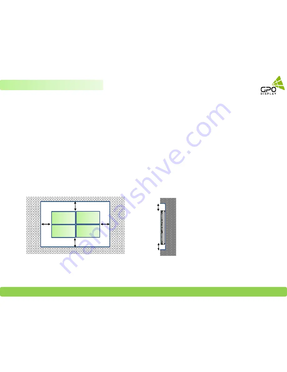
Dimensions below are minimum required for proper ventilation and movement of displays within H-Mount structure

3”

2” 

* Note:

Ventilation space must not be covered or closed off at the 

front of the opening. If for some reason the opening 

needs to be covered, other means of ventilation will need 

to be incorporated into the design. Contact GPO Display 

for design review and recommendations.

6

Chapter 1  Precautions

Clearance Spec: 3.5” (Left/Right), 3” (Top), 2” (Bottom)

3”

2” 

3.

5”


3.

5”

Summary of Contents for GDSVW775

Page 1: ...GPO Display Video Walls Commercial Monitors Digital Signage Visual Solutions www gpodisplay com Installation Manual HLM Mount Ver 1 0 1 ...

Page 2: ...play tech support or call a qualified contractor GPO Display is not liable for damage or injury caused by incorrect mounting assembly or use If mounting to wood wall studs make sure that mounting screws are anchored into the center of the studs Use of an edge to edge stud finder is highly recommended Tighten screws firmly but do not overtighten Overtightening can damage or warp the items greatly r...

Page 3: ...htened and secured on the wall The Liquid Crystal Display LCD panel of the display has a very thin protective layer of coating which is susceptible to marking or scratching and cracking if struck or pressured Please cover and protect the displays if there is construction or other work being conducted at the installation site Transport and handle displays by holding the handles on the back of the d...

Page 4: ...the display face panel side down Prepare a flat level horizontal surface that is larger than the display and spread a thick protective sheet foam on it Fig 1 Lay the display down gently and horizontally When you want to place the display in an upright position Lift the display up horizontally by holding the two 2 handles at the top rear with one hand per person and supporting the bottom bezel with...

Page 5: ...ed by sliding a standard business card between the gap if there is no resistance the gap is sufficient Recommended gap between displays 0 5mm Do not tilt displays in a manner that would result in pressure on the panel edges If backlight leakage as shown below is evident this is a sign of excessive pressure and adjustment to the alignment of the array must take place If more than 1kg of weight is a...

Page 6: ... table Avoid displaying static images for prolonged periods of time Avoid content with significant brightness differences Dimensions below are minimum required for proper ventilation and movement of displays within H Mount structure 3 2 Note Ventilation space must not be covered or closed off at the front of the opening If for some reason the opening needs to be covered other means of ventilation ...

Page 7: ...be installed Do not plug more than two units into a given receptacle example all displays in 2x2 should not be plugged into quad receptacle Using more than 70 of current on the AC circuit is strongly discouraged Clean AC power is required for noiseless screen images Avoid damages inflicted by power glitches or surges either a power conditioner or surge protector is recommended Contact your electri...

Page 8: ...p with USB to RS 232 adapter Drill w metal wood and mortar bits Phillips head screwdriver Tape Measure Level Socket Set Wrench set Shims metal or wooden for alignment adjustment when a wall is uneven Cable ties for final cable dressing Screen cleaner and lint free cloth for final cleanup This is a bare minimum list review statement of work to determine all tools needed Supporting Documents and Sof...

Page 9: ...5 Recommend Receiver Decoder Media Players Positions A or C 9 Positioning Chapter 2 Preparations HLM46T HLM46TE Device placement A C B A C zones 2 35 W x 15 H x 2 2 Depth for Third party placement The area outlined in red 6 x 15 is available if the device is under 1 8 in depth B zone 10 x 15 x 2 2 Depth for Power Outlet HLM55T HLM55TE Device placement A C zone 5 x 15 x 2 2 Depth for Third party pl...

Page 10: ...nage Visual Solutions www gpodisplay com 10 Chapter 2 Preparations Tip Third party player placement Device inputs output terminals should be positioned facing to the left as shown in the image to the right Devices Receiver decoder Distribution Amplifier etc ...

Page 11: ...the wall as shown in the drawing to the right A B 1 Construct the reinforcement frame to match specifications set forth by GPO Display 2 Continue constructing the reinforcement frame adding cross bar supports where necessary 3 Affix Z Shift wall mounts to reinforcement frame as shown in the image to the right Be sure to bolt the Z Shift mounts to one another using the M8 bolts provided by GPO Disp...

Page 12: ...tion of the side to side movement of the screens within the Z Shift mount structure When plywood backing is used ensure that there are holes of sufficient size to run all necessary cabling 3 Assemble the mounts affix to one another using interconnecting M8 bolts and ensure that they are level as instructed previously in this manual 2 Affix H mounts in the manner shown in the image on the right fol...

Page 13: ...ised of more than 99 displays A 3x3 array will be used as an example in the following pages Contact GPO Display if you are unsure about how to apply these instructions and concepts to other video wall array configurations STEP 1 Verify that installation location is ready power network wall reinforced adequate ventilation coax cable if being installed Verify all necessary tools are ready to use Ope...

Page 14: ...ith lag screws M4 20L Ensure that these mounts are level Tips for 2x2 or 3x3 video wall arrays If your array is a 2x2 array or 2x1 or 1x2 you may pre assemble mounts For example this means that you may use the M8 interconnecting bolts to construct a 2x2 frame prior to hanging the mounts on the wall using The lag screws This will help save time for these smaller arrays The mounts shown to the right...

Page 15: ...ount to Wall or Wall Reinforcement frame with lag screws M4 20L Check level again Use M8 interconnecting bolts corresponding nuts to connect the fourth mount to the first mount Next affix fourth mount to Wall or Wall Reinforcement frame with lag screws M4 20L Check with level again 3 1 2 4 3 1 2 4 5 6 For 3x3 arrays you may assemble rows of mounts on the floor prior to attaching them to the wall S...

Page 16: ...nt frame with lag screws M4 20L Check level again For 3x3 arrays you may assemble rows of mounts on the ground prior to attaching them to the wall See example of third top and final row to the right Note Floor surface must be level even when connecting mounts 9 7 8 Tip for 2x2 or 3x3 video wall arrays 3 1 2 4 5 6 7 8 9 Use M8 interconnecting bolts corresponding nuts to connect the seventh mount to...

Page 17: ...nt there are two insertion positions located at the bottom left right of the mount Turn Y Knob clockwise until 1mm of the bolt is visible stop the Y Adjustment plate The image shown to the bottom right shows the Y Knob inserted further than needed during initial installation Make sure that the end of the bolt does not protrude more than 1mm above the Y Adjustment plate prior to installation of the...

Page 18: ...tight as to prevent future movement pulling of cables 18 Organize Cables and Devices STEP 4 2 Recommended cable paths shown on the right Position all cables before display is mounted Locate the cable tie mounts in the center of the mount structure rather than the bottom or top 3 Locate mount all devices before display is mounted Chapter 3 Mounts Installation Example shown above is 55 ...

Page 19: ... to the panel 2 Lay the back of the Set down on a table LCD panel facing upward 3 Power the display on and check for a no signal message Assign the display s Set ID using the remote controller provided in the accessories box and make a note of this Set ID number Power the display off See OSD interfaces on the right For more detailed information on this process consult the display user manual 19 Pr...

Page 20: ...ervice Channel Used for mounting and most dismounting cases Opening This is a safety mechanism used to alert technicians when the display is about to drop into a lower channel either from the upper channel or from the center channel Installation channel Used for convenient dismounting when displays are in lower channel Resting Position This is where the display is seated when installation is compl...

Page 21: ...y and its corresponding H Mount has the same width height When installing displays note that the service opening is positioned so that the display outline will sit 1 4 higher than the mount outline when the pegs are aligned with the service opening Horizontal guide notches on the bottom corners of the H Mount frame help to guide the display position during the mounting process showing whether the ...

Page 22: ...ll a display directly above the previously mounted display After inserting the pegs in the opening slowly carefully ease the display down until it comes to in the installation channel Make sure that the display is eased down into the installation channel evenly if one side is dropped too quickly damage to the previously installed display may occur Refer to p 5 for more information on recommended g...

Page 23: ...mpact the right column of displays with force Repeat the same steps taken for the right column of displays with the center column of displays 3 Set ID 6 2 Set ID 9 1 Set ID 3 Set ID 8 4 3 Set ID 6 2 Set ID 9 1 Set ID 3 Set ID 8 4 Set ID 5 5 Set ID 2 6 Chapter 4 Display Mounting 3 Set ID 6 2 Set ID 9 1 Set ID 3 Set ID 8 4 Set ID 5 5 Set ID 2 6 Set ID 7 7 Set ID 4 8 Set ID 1 9 Repeat the same steps ...

Page 24: ... push a given corner of a display outward from the wall moving the corner of the display forward slightly 24 Chapter 5 Alignment Z BOLT Tip Displays naturally tilt downward meaning the top protrudes slightly more than the bottom In order to make Z Axis adjustments push very gently with an open gloved palm on the top of the display and then engage the bottom Z Bolts by turning counter clockwise STE...

Page 25: ...se adjustments in minor increments and exercise caution when returning neighboring displays to their final installed position Y axis adjustments may lead to displays sitting on top of displays below causing excessive pressure on bezels 25 Chapter 5 Alignment Case 1 Case 2 Y Knob STEP 1 Turn the outer Y knobs 1 and 4 clockwise to move the displays upward as needed to achieve Y Axis alignment Turn t...

Page 26: ...accounted for during the installation process To ensure proper alignment on the X axis ensure that all mounts are in line with one another prior to hanging displays The application of side covers will lock displays in line with the mounts on the X axis preventing any drift Alignment X Axis 26 Chapter 5 Alignment Display 3 4 Peg 3 4 ...

Page 27: ...to the left Look over the wall for alignment issues from various angles Chapter 5 Alignment Move center column of displays to centered position resting position 3 Set ID 6 2 Set ID 9 1 Set ID 3 Set ID 8 4 Set ID 5 5 Set ID 2 6 Set ID 7 7 Set ID 4 8 Set ID 1 9 3 Set ID 6 2 Set ID 9 1 Set ID 3 Set ID 8 4 Set ID 5 5 Set ID 2 6 Set ID 7 7 Set ID 4 8 Set ID 1 9 ...

Page 28: ... bolts with the backend of 1 The heads of 2 s Z bolts should align with the back of display 1 Slide 2 back toward 1 to the right in its resting position You may need to pull out on 2 slightly as you move it over to the right 4 After making this adjustment adjust 2 s Y knobs to match level with 1 see p 25 for more details on Y Knob adjustments 5 Follow the same steps on 3 with the directions revers...

Page 29: ...om 29 Finish STEP 6 Affix side covers shown outlined in red bottom right by screwing into mounts Use the FH M 4 8L screws provided Attach side cover by inserting screws into the outer sides of H Mounts on the perimeter of the array SCREW FH M 4 8L for Side Covers Side Cover Chapter 5 Alignment ...

Page 30: ...bs of s 7 and 8 by turning counter clockwise Slide s 7 and 8 to the left Follow the same steps on s 4 and 5 Follow the same steps on s 1 and 2 Move Set 3 into the Upper Service Channel Move Set 6 into the Lower Service Channel Remove cabling from Set 9 Carefully lift 9 up 1 4 so that the pegs align with the opening bottom of Set 9 will align with corner guidelines on mount Gently pull 9 outward Fr...

Page 31: ...ld they arise Some installation sites have a high level of Electric Noise which may appear onscreen especially with DVI DVI HDMI and DisplayPort are HDCP compliant Signal looping specifications Video signals should be boosted by using a distribution amplifier when more than four 4 units are connected via DVI NSV EN series or nine 9 units are connected via HDMI EK series See tables below Chapter 7 ...

Page 32: ...its tested during production While GPO Display can make no guarantees RS 232 daisy chaining should be able to take place on up to 25 displays Daisy chaining can be initiated from any unit but it is strongly recommended that you start with a display on the bottom row for ease of access There is no terminator at the end of the unit It is always recommended to record make note of the chaining diagram...

Page 33: ...nect Video Cables Daisy Chain EK Series 33 Chapter 7 Cabling Setup HDMI IN HDMI Out HDMI IN HDMI Out HDMI IN HDMI Out HDMI IN HDMI Out HDMI IN HDMI Out HDMI IN HDMI Out HDMI IN HDMI Out HDMI IN HDMI Out HDMI IN HDMI Out Set ID 1 Set ID 2 Set ID 3 Set ID 4 Set ID 5 Set ID 6 Set ID 7 Set ID 8 Set ID 9 ...

Page 34: ...iently located display typically bottom left or right Connect aforementioned display to signal distributor using the DVI output Use Signal Distributor outputs to connect to displays in each vertical column as shown on right When using D A connect individual displays via DVI daisy chain in order from bottom to top using DVI cables as shown top right 34 Chapter 7 Cabling Setup Daisy Chain Connection...

Page 35: ...ys from a device residing upstream in the RS232 path The ACR Hub serves as an IR extender for the remote controller ex Users can power the video wall monitor ON OFF Must change Set ID on ACR Hub to 00 to address all sets Select Set ID 00 on the ACR Hub to address all displays in the RS232 daisy chain via remote controller Users can toggle display Power On Off via remote control by pointing the rem...

Page 36: ...GPO Display Video Walls Commercial Monitors Digital Signage Visual Solutions www gpodisplay com 36 Device placement ...

Page 37: ...GPO Display Video Walls Commercial Monitors Digital Signage Visual Solutions www gpodisplay com 37 Device placement ...

Page 38: ...GPO Display Video Walls Commercial Monitors Digital Signage Visual Solutions www gpodisplay com 38 H Mount Device placement ...

Reviews: