


Supplied By www.heating spares.co Tel. 0161 620 6677
20
221679H
7034
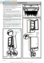
Diagram 10.1
BURNER
PRESSURE TEST
POINT
GAS CONTROL
VALVE
WARNING
230V 50Hz
ELECTRICAL
CONNECTIONS
Please ensure the “Benchmark” logbook is completed and left
with the user.
10.1 Filling Domestic Water Circuit
Check that the boiler is isolated from the electrical supply, at the
external isolator.
Fully open the domestic water supply stop cock or valve in the
supply to the boiler.
Open the domestic water isolation valve, lever in line with the
valve body, see diagram 6.1.
Open all hot water draw-off taps and close them when water
flows. Check for water soundness of the whole domestic water
system and boiler.
10.2 Filling the Heating System
Open the two central heating isolating valves, levers in line with
the valve body, see diagram 6.1.
Flush, fill and vent the system refer to Section 4.8 “Filling
Sealed Systems”.
WARNING. SEVERAL COMPONENTS OPERATE ON MAINS
VOLTAGE AND WITH THE OUTER CASE REMOVED, LIVE
COMPONENTS BECOME EXPOSED.
To assist in filling and venting, the pump may be operated:
Connect the electrical supply, refer to diagram 4 "Instructions
for Use", set button “J” to “winter”, “F” will illuminate, set any
remote heating systems controls, time switch and/or room
thermostat to call for heat.
Note. If the clock/timer kit is to be fitted, refer to the setting
instructions in the Instructions for Use.
Make sure that the automatic air vent is operating correctly.
Take care not to splash any of the electrical components.
Open the controls cover.
Refer to diagram 4 "Instructions for Use". Operate button “J”
between “H” summer and “F” winter to ensure that water flows
through all parts of the boiler and air is not trapped in the boiler
internal bypass.
Pressurise the system until the pressure is 1.5bar (21.5lbf/in2).
Check the heating system and boiler for water soundness.
Check the operation of the safety valve by turning the safety
valve knob in the direction of the arrow.
Lower the pressure to the initial cold fill design pressure, refer
to Table 1. Position the set pointer on the boiler pressure gauge
at this pressure also.
Refit inner case front.
10.3 Preparation for Lighting
Turn on the gas service cock, slot in line with the length of the
cock.
Test for soundness and purge air from the gas supply.
Switch power 'ON' at the mains electrical supply at the external
isolator and switch at the boiler.
Light the pilot refer to relevant parts of "Light the boiler"
(Instructions for Use).
Loosen the burner pressure test point screw and connect a
suitable pressure gauge, see diagram 10.1.
10 Commissioning
10.4 Burner Pressure - Hot Water
Connect the electrical supply it will default to winter, select
summer, the pump will operate for about 30 seconds then the
pump will stop.
Fully open the largest hot water draw off tap whereby the main
burner will light, the flames gradually increasing to the maximum.
Check the soundness of the boiler gas joints, with the main
burner on, using a leak detection fluid. Take care not to splash
any of the electrical components.
To achieve this flow rate a water pressure of at least 0.8bar is
required during commissioning, although subsequently the
appliance will work at a minimum pressure of 0.5bar.
This flow rate should prevent any modulation of the gas pressure.
The burner pressure is factory preset and no adjustment should
be required.
Check the burner pressure is /-0.35mbar (+/-0.14in wg).
of 13.0mbar (5.22in wg). If this is incorrect, the burner pressure
may be adjusted to the correct setting by turning the hot water
gas pressure adjuster (potentiometer), located on the control
board to gain access remove the two screws securing the
controls facia, see diagram 9.1.
Hinge the control facia forward.
Remove the plastic plugs. Using the burner adjusting tool
supplied. (Clockwise to increase), see diagram 10.2. Turn the
adjuster slowly, always making adjustment by reducing below
the required pressure then increasing up to the required setting.
Close the hot water draw off.
If the maximum pressure cannot be obtained, check that the gas
supply is of adequate size, refer to Section 1.7.
10.5 Gas Rate Modulation
The minimum gas rate is factory preset and no adjustment
should be required.
ALWAYS CHECK HOT WATER BURNER PRESSURE FIRST
- REFER TO SECTION 10.4.
To check the minimum gas rate, first make sure that the boiler
is isolated from the electrical supply at the external isolator


