


Supplied By www.heating spares.co Tel. 0161 620 6677
32
221679H
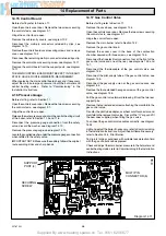
14.1 Fan
Before starting refer to Section 11.
Disconnect the two electrical connectors at the fan by pulling the
boots not the wires, see diagram 8.2.
Disconnect the two air pressure switch flexible tubes from the
fan.
Remove the fan, secured with two screws at the front and gently
ease the fan from the flue elbow and rear bracket.
To fit the fan, locate it into the rear bracket and ease the fan into
the flue outlet, secure with the two screws.
The polarity of the two electrical connectors is not important.
14.2 Main Burner
Before starting refer to Section 11.
Remove the two screws securing the flue collector, see diagram
14.1.
Remove the combustion chamber front panel, secured with four
screws.
Open the controls cover door, see diagram 4.
Remove the two screws securing the controls facia, see diagram
9.1.
Hinge the control facia open.
Separate the pilot assembly from the main burner secured with
two screws and washers, see diagram 14.2.
Remove the sealing gland, see diagram 14.2.
Remove the burner bracket securing screw, wing nut and
bracket, see diagram 14.2.
Remove the main burner from the main injector at the rear. Tilt
burner up and slide in channel forwards, easing the pilot
assembly forwards to clear, taking care not to damage the
combustion chamber insulation or the pilot burner assembly.
When refitting make sure that the main burner is fitted correctly
on assembly, located on the main injector and horizontal, the
tips of the rearmost blade under the two burner guides.
Locate the combustion chamber front panel under the front
edge of the flue hood on assembly, then secure all screws and
wing nut.
Test pilot for gas soundness with suitable leak detection fluid
with the gas control knob depressed.
14.3 Main Injector
Before starting refer to Section 11.
Remove the main burner, refer to Section 14.2.
Unscrew the main injector, see diagram 14.3.
Fit the new sealing washer supplied, to ensure gas soundness,
when fitting the main injector.
14.4. Pilot Burner
Before starting refer to Section 11.
Remove the main burner refer to Section 14.2.
Remove the sealing angle, secured with a single screw, see
diagram 14.2.
Remove the spark electrode, secured with a spring clip, see
diagram 14.2.
Disconnect the thermocouple nut from the pilot burner.
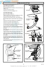
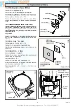
14 Replacement of Parts
Diagram 14.1
7249
WINGNUT
COMBUSTION
CHAMBER
FRONT PANEL
FLUE
COLLECTOR
SCREW (4)
SECURING
SCREW (2)
Diagram 14.2
SPARK
ELECTRODE
IGNITION
LEAD
PILOT INJECTOR
SPARK
ELECTRODE
RETAINING CLIP
THERMO-
COUPLE
NUT
PILOT TUBE
NUT
WING NUT
SECURING
SCREW AND
WASHER (2)
SEALING GLAND
SECURING SCREW
4583
SECURING
SCREW
BURNER BRACKET


