


Supplied By www.heating spares.co Tel. 0161 620 6677
24
221679H
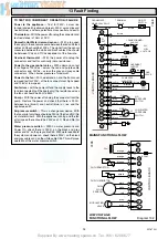
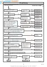
Diagram 13.1
7025
CLOCK/TIMER
PLUG
LINK
CLOCK/TIMER
12.7 Operational Checks
Check the safety valve manually by turning the knob in the
direction of the arrow.
Light the boiler, carry out operational checks and any necessary
adjustments as described in Commissioning in the Installation
Instructions.
12 Servicing
13.1 Initial Checks
If the boiler fails to operate, first check the following:-
1) That the electrical supply is available at the boiler and the
fuses are in order. The mains light should be ON. If not isolate
the boiler from the electrical supply.
Test for continuity, at mains.
NOTE: THE BOILER CONTROL BOARDS CAN BE DAMAGED
BY INCORRECT TESTING OF COMPONENTS AND WIRING
WITH THE POWER ON.
2) Make sure that the system pressure gauge registers 0.7bar,
minimum, and that the automatic air vent works. Refer to
Installation Instructions, Section 10.2.
3) That the gas supply is available at the boiler and purged of
air.
4) That the boiler is set for the required service.
5) With the boiler Summer/Winter Button “J” set to summer “H”,
see diagram 4 User Instructions, check that the domestic water
supply is available and water flows freely from the hot taps.
Close the taps.
6) With the boiler Summer/Winter Button “J” set to Winter “F”,
see diagram 4 User Instructions, check that all heating system
controls, if fitted, are working correctly and calling for heat.
7) Check Summer/Winter Button “J” is set to Winter “F”, see
diagram 4 User Instructions. Turn on a domestic hot water draw
off tap to create a demand.
Allow the boiler and system to cool down waiting at least a
minimum of four minutes before pressing Summer/Winter Button
“J” to set to Winter “F”.
If this is satisfactory proceed with the detailed fault finding as
Section 13.3.
13.2 Clock/Timer
If the clock has failed it can be bypassed by disconnecting the
plug and reconnecting the link, see diagram 13.1.
Gain access by removing the two screws securing the controls
facia, see diagram 10.1.
Hinge the control facia forward.
Remove the clock timer cover, see diagram 9.1.
Disconnect the clock wiring harness plug and connect the link.
This is a temporary measure and the clock should be repaired
or replaced as soon as possible.
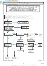
13.3 Electrical
Preliminary electrical system checks, as outlined in a Multimeter
Instruction book, are the first checks to be carried out during a
fault finding procedure.
Isolate the boiler from the electrical supply, refer to Section
11.3.
Gain access to the boiler controls by removing the outer case
front, refer to diagram 10.5.
Remove the two screws securing the controls facia, see diagram
9.1.
Hinge the control facia forward.
Remove the cable entry cover, see diagram 10.2.
Remove the controls cover
Check that all cables and connectors are secure.
Check all cables at the multipin connectors on the board.
Test the fuse on the main control board and renew as necessary.
Fuse F1 type (2AT and F2 315mAT). If a fuse fails repeatedly
or the initial fault-finding checks described in Section 13.1
indicate a boiler fault, check the boiler electrical circuits and
follow the fault finding procedures, see diagram 13.2 mains
functional flow, 13.3 pilot fault finding, 13.4 boiler fault finding
13.5 thermocouple fault finding and for clock/timer fault finding,
diagrams 13.6 and 13.7.
On completion of a fault finding task that has required the
disconnection and making of electrical connections then checks,
for earth continuity, polarity and resistance to earth must be
carried out.
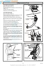
Before replacing any part please read points below:-
Replacement of parts must only be carried out by a competent
person.
1. Refer to Section 11.1.
2. Always isolate the boiler from the electrical and as required,
the gas supply, as Section 11.3.
3. On completion, make good any water loss and pressurise the
system to initial design pressure, refer to “Commissioning” in
the Installation Instructions.
Before starting refer to Section 11.1
Isolate the boiler from the electrical supply, refer to Section
11.3.
12.8 Completion
Hook the outer case front on the top and secure with the nuts
previously removed, see diagram 10.5.
13 Fault Finding


