


Supplied By www.heating spares.co Tel. 0161 620 6677
16
221679H
Diagram 8.1
7232
INNER
CASE
FRONT
SECURING
SCREW (4)
Diagram 8.2
7234
ELECTRICAL
CONNECTORS
SECURING
SCREW (2)
REAR
BRACKET
FLUE
COLLECTOR
RED AIR PRESSURE
SWITCH TUBES
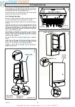
8 Mounting the boiler and Flue Fitting
8.1 Boiler Mounting
Remove the inner case front, see diagram 8.1.
To assist with the location of the flue elbow into the fan outlet
remove the fan by removing the securing screws, the electrical
connections by pulling the boots not the wires and air pressure
switch tubes, see diagram 8.2.
Remove the protective caps from the boiler water pipes
Fit the sealing washers (supplied in the fittings pack) to the
boiler water pipes by inseting them into the tubing nuts. (the
nipples on the washers will hold them in position), see diagram
8.4.
Lift the boiler into position on the top mounting brackets, see
diagram 8.3.
8.2 Water and Gas Connections
Locate the boiler water pipes and gas supply pipe, making sure
the washers are retained in the tubing nuts, onto the isolation
valves, fully push the boiler back, see diagram 8.4.
Ensure the bottom boiler bracket is sitting on top of the service
cock bracket, see diagram 8.3.
Fit the flow restrictor into the domestic water inlet, see diagram
8.4.
Secure all tubing nuts finger tight, plus
3
/
4
turn maximum.
Connect the gas pipe to the isolation valve ensuring that the
sealing washer (supplied fitted) is in position.
8.3 Boiler Securing
Secure the boiler with the two boiler securing screws supplied
loose, to the service cock bracket, see diagram 8.3.
An anti theft kit is available, Kit No. 457110
8.4 Flue Fixing to the Boiler
Make sure that the ductings do not slope down towards the
boiler.
Position the restrictor plate supplied in the loose items pack,
between the flue elbow and boiler , (gasket facing upwards). Fit
the flue elbow to the restrictor plate and top of the boiler using
the four screws supplied, see diagram 8.5.
Tighten the four screws of the flue elbow evenly to ensure a
good seal at the gasket.
Make the wall good internally and externally around the air duct,
also making it weatherproof on the outer wall a flue collar kit is
available Pt. No. 443286.
Refit fan retained by the rear bracket and two securing screws.
Refit the inner case front.
FAN
WHITE AIR
PRESSURE
SWITCH
TUBES


