


Supplied By www.heating spares.co Tel. 0161 620 6677
13
221679H
7028
UNION
CONNECTION
DISCHARGE
PIPE
SAFETY
VALVE
DISCHARGE
Diagram 6.2
SEALING
WASHER
REAR VIEW
OF BOILER
The installation requires the following components :-
1.
Plumbing jig Carton
2.
Boiler Carton
3.
Flue Pack
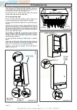
6.1. Plumbing Jig
Remove from the carton the wall template, then follow the
instructions given on the template.
Note: It is important that the wall hanging bracket and the
service cock bracket are fitted to a flat and true wall area for
correct alignment with the boiler. Where this cannot be achieved
it is acceptable to pack out the service cock bracket to obtain the
correct alignment with the wall hanging bracket.
6.2 Gas Connection
Provision is made for the gas supply to be connected from
below the boiler, see diagrams 1.1 and 6.1 for position.
Refer also to “Gas Supply”, Section 1.7.
Make the gas supply connection to the gas service cock. While
making the connection, do not subject the gas service cock to
heat as you may damage the seals. Purge the gas supply.
6.3 Water Connections
Provision is made for the domestic cold water inlet to be
connected from below or through an internal wall at the rear of
the boiler, see diagram 1.1 and 6.1 for position.
Refer also to Section 5 “Domestic Hot Water System”.
Provision is made for the water connections to be connected
from below or from above, passing down either side of the
boiler. Take care that any pipework connected from above will
clear the expansion vessel. Refer to the wall template. If
connecting from above a piping kit 457160 is available and is
recommended. If necessary, temporarily fit the boiler.
Flush out the domestic water and heating system before
connecting the boiler.
Make the connections to the domestic hot water outlet and the
heating system by means of the isolating valves, see diagram
6.1.
While making the connections. Do not subject any of the
isolating valves to heat as you may damage the seals.
Make sure that the drain screw heads on the isolating valves are
accessible.
6.4 Safety Valve Discharge
WARNING. It must not discharge above an entrance or window
or any type of public access area.
A short discharge pipe is supplied loose with the boiler, which
when fitted to the safety valve, will end below the boiler the
position is next to the heating return, see diagram 6.2. (THE
DISCHARGE PIPE MUST BE FITTED BEFORE THE BOILER
IS MOUNTED ON THE WALL).
This must be extended, using not less than 15mm od metal
pipe, to discharge, in a visible position, outside the building,
facing downwards, preferably over a drain. The pipe must have
a continuous fall and be routed to a position so that any
discharge of water, possibly boiling, or steam cannot create any
danger to persons, damage to property or external electrical
components and wiring.
Note. To ease future servicing it is advisable to use a compression
type fitting to extend the discharge pipe.
6 Installation Preparation and Gas / Water Connections
Diagram 6.1
6956
GAS
SERVICE
COCK
HOT
WATER
OUT
COLD
WATER
SUPPLY
IN
HEATING
FLOW
HEATING
RETURN
SLOT (OPEN)
COLD WATER
SUPPLY IN/OUT
SLOT (OPEN)
GAS SERVICE
COCK
SLOT (OPEN)
HEATING
FLOW/ RETURN
SAFETY DISCHARGE
PIPE ROUTING POSITION


