


Supplied By www.heating spares.co Tel. 0161 620 6677
21
221679H
10 Commissioning
Remove grey wire from the modureg coil (insulate from sheet
metal).
Switch on the electrical supply it will default to winter, select
summer.
Fully open a hot water draw off tap and the main burner will light
at the minimum gas rate.
Check that the burner pressure is 1.2mbar +/-0.2mbar, (0.5in
wg +/-0.1in wg). If this is incorrect, it may be adjusted by
removing the cap and turning the larger adjusting nut of the
modulator, (anticlockwise to decrease the pressure).
If the above adjustment was necessary, it will be essential to
check that the maximum pressure can still be obtained. Push
the spindle gently in to the stop and hold it in. The maximum
pressure should not be less than 14.5mbar, (5.8in wg). If this
pressure cannot be achieved, obtain it by turning the small
adjusting nut, (clockwise to increase the pressure). Always
adjust the minimum pressure first. Reconnect the grey wire and
adjust pressures on potentiometers.
If the maximum pressure is unattainable, check that the gas
supply is of adequate size, refer to Section 1.7 “Gas Supply”.
Put right as necessary.
Isolate the boiler from the electrical supply then reconnect the
modulator cable and refit the cap.
10.6 Domestic Water Flow Rate
This is factory preset and can not be adjusted.
10.7 Burner Pressure - Heating
The burner pressure is factory preset and no adjustment should
be required.
Check that all remote heating system controls, room thermostats,
integral clock and the like are switched on/programmed and
calling for heat.
Set button “J” to “winter” “F”, see diagram 4.
The pump will circulate water through the boiler and the main
burner will light.
Check that the burner pressure, with the heating system cold to
prevent any modulation of the gas pressure, is /-
0.2mbar (+/-0.08in wg) of 7.6mbar (3.05in wg), the central
heating pressure.
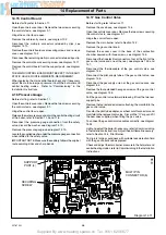
If the burner pressure is incorrect, it may be adjusted to the
correct setting by turning the central heating gas pressure
adjuster (potentiometer), located on the control board to gain
access remove the two screws securing the controls facia.
Hinge the control facia open.
Remove the plastic plugs. Using the burner adjusting tool
supplied (clockwise to increase), see diagram 10.2. Turn the
adjuster slowly, always making adjustment by reducing below
the required pressure then increasing up to the required setting.
Isolate the boiler from the electrical supply.
Remove the pressure gauge and tighten the test point screw.
Test for gas soundness around the burner pressure test point
with the main burner alight, using leak detection fluid. Take care
not to splash any of electrical components.
Replace plastic plugs and refit the control fascia.
10.8 Temperature Settings
The domestic hot water outlet and central heating flow
temperatures are factory preset and sealed, therefore cannot
be adjusted.
The nominal temperature setting for the domestic hot water
outlet is 65
o
C (149
o
F) at a flow rate of 3.6Litre/min (0.8gall/min).
The nominal maximum flow temperature setting for central
heating is 82
o
C (180
o
F).
10.9 Heating System - Commissioning
Check that all remote controls and integral clock are calling for
heat.
Fully open all radiator valves.
Set the heating system in operation and balance the radiators.
Refer to Section 4.6 and diagram 4.1.
Allow the system to reach maximum temperature then switch
off, isolate the boiler from the electrical supply and drain the
system rapidly whilst still hot.
Remove the inner case front.
Fill and vent the system as described in Section 10.2 “Filling the
Central Heating Circuit”. Add inhibitor, if applicable, refer to
Section 4.9 “Corrosion Inhibitor”.
Lower the pressure to the initial cold fill design pressure, using
the external draining tap, close to the boiler, refer to Table 1 and
Section 4.10.
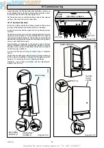
10.10 Completion
Refit the inner case front.
Fit the side panels, hook into the threaded lugs at the top, see
diagram 10.3.
Fit the case base, slide back engage the rear lugs, secure with
two screws supplied, see diagram 10.4.
Secure the side panels at the bottom with the four screws, see
diagram 10.3.
Fit the outer case front by locating it on one side then wrap it
7078
Diagram 10.2
CABLE ENTRY
COVER
CLOCK-TIMER
COVER
CONTROL
BOARD
COVER
BURNER PRESSURE
ADJUSTING TOOL
DOMESTIC HOT WATER BURNER
PRESSURE POTENTIOMETER
HEATING BURNER
PRESSURE
POTENTIOMETER
PLASTIC
PLUG (2)
CONTROL
BOARD
COVER
SECURING
SCREW (4)


