


Supplied By www.heating spares.co Tel. 0161 620 6677
25
221679H
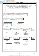
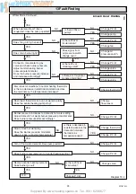
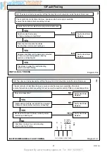
13 Fault Finding
7468
7495
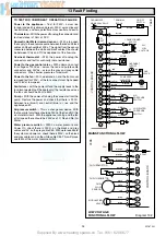
Diagram 13.2
MAINS FUNCTIONAL FLOW
TO TEST FOR COMPONENT OPERATION / FAILURE
Power to the appliance :-
Test for 230V~ across live
(brown) and earth (yellow and green), 230V~ across live and
neutral (blue), and zero potential across neutral and earth.
Thermistors :-
With the power off unplug the connector and
test resistance is 10k
Ω
at 25
°
C.
Domestic Hot Water demand sensor :-
With a tap open
the supply to the sensor measure between the red and black
cables on X5a should be 12Vdc. The signal from the sensor
measured between the white and black cables X5a should
be between 1Vdc and 11Vdc dependent of the flow rate.
Overheat thermostat :-
With the power off unplug the
connectors and test for continuity (zero resistance).
Power to the gas control valve :-
With a demand on
test
for voltages of
230Vac ~ across the red and purple cable
connectors and 24Vdc ~ across the grey and grey cable
connectors. When burner pressure at maximum.
Power to the fan :-
With a demand on and the front cover
removed test for 230V~ at the fan connectors at high speed
and 108V at low speed
Fan failure :-
with the power off and the supply leads to the
fan disconnected (pull the boots only) the resistance across
the fan coil should be 45
Ω
to 50
Ω
.
Pump :-
With the power off unplug the connector from the
pump. Restore the power and check that there is 230V~
between live (brown) and neutral (blue) or live and the
appliance earth.
Air pressure switch :-
This is a change over device. With
the fan at pilot only there should be 230V at the C and NC (No
air state terminals. With the appliance running and the fan
at full speed there should be 230Vac at C, Nc and No (Air
State).
Water pressure switch :-
With no water pressure and
Power On, check there is 230V~ on the black and grey
cables and 0V on the grey cable X5b. With water applied to
the system and power on, check there is 230V~ on the black
and grey cables and on the white cable X5b. This will prove
operation of the water pressure switch.
LOW VOLTAGE
FUNCTIONAL FLOW
F1
2AT
red
red
red
red
purple
brown
yellow
blue
brown
brown
brown
brown
blue
N
OVERHEAT
CUTOFF
CONTROL BOARD
GAS
VALVE
ON/OFF
SWITCH
TERMINAL
BLOCK
PERMANENT
MAINS 230V-50HZ
FAN
PUMP
TRANSFORMER
240/24V
24V
LOW
VOLTAGE
X3
X3
X4
X4
X3
X3
X2
X2
X2
X2
X2
X2
X2
X2
L
N/C
N/O
N/C2
N/O4
C
grey
red
violet
AIR
PRESSURE
SWITCH
X5b
X5b
X5b
C1
grey
black
blue
white
LOW WATER
PRESSURE
SWITCH
FAN SPEED
RESISTOR
brown
3.15AT
grey
grey
red
white
black
X6
X6
X6
MODULATING
VALVE
DHW
FLOW
SENSOR
purple
purple
DHW THERMISTOR
orange
orange
orange
orange
X6
X1
X1
CH THERMISTOR
24v~
CONTROL BOARD
X5a
X5a
X5a
X5a
X5a


