


Supplied By www.heating spares.co Tel. 0161 620 6677
37
221679H
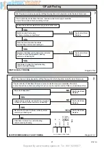
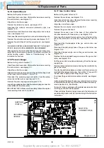
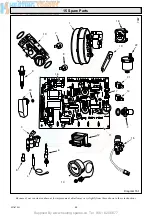
14 Replacement of Parts
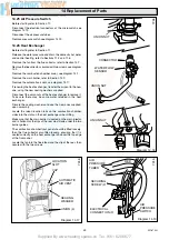
Diagram 14.12
7089
Diagram 14.13
7026
SAFETY
VALVE
WASHER
UNION NUT
SECURING
SCREW (2)
FASCIA
RETAINING
BRACKET (2)
PRESSURE
GAUGE
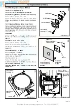
Diagram 14.14
7247
ELECTRICAL
CONNECTOR
(2)
MODULATOR
SCREW
(2)
GAS
CONTROL
VALVE
GASKET
Diagram 14.15
7035
AUTOMATIC
BYPASS VALVE
UNION NUTS
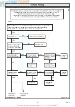
14.18 Modulator
Before starting refer to Section 11.
Open the controls cover door. Remove the two screws securing
the controls facia, see diagram 9.1.
Hinge the control fascia open.
Disconnect the two electrical connectors at the modulator, see
diagram 14.14.
Remove the modulator, secured with two screws.
Discard the gasket and fit the new one supplied with the
modulator.
Light, check and adjust the boiler if necessary, refer to
Commissioning in the Installation Instructions.
Test joints for gas soundness with suitable leak detection fluid
with the gas control knob depressed.
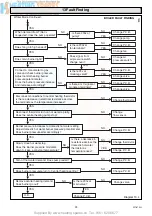
14.19 Automatic Bypass Valve
Before starting refer to Section 11.
Remove the case base, see diagram 10.4.
Open the controls cover door. Remove the two screws securing
the controls facia, see diagram 9.1.
Hinge the control fascia open.
Isolate the central heating flow and return, release the water
pressure and drain, refer to Section 11.3 and 11.6.
Remove the pressure automatic bypass valve by disconnecting
the union nuts, see diagram 14.15.
Discard the sealing washers and use the new ones supplied.
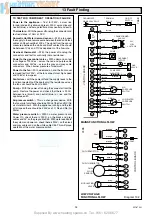
14.20 Safety Valve
Before starting, refer to Section 11.
Remove the case base, see diagram 10.4.
Open the controls cover door. Remove the two screws securing
the controls facia, see diagram 9.1.
Hinge the control fascia open.
Release the water pressure and drain, refer to
Sections 11.3 and 11.6.


