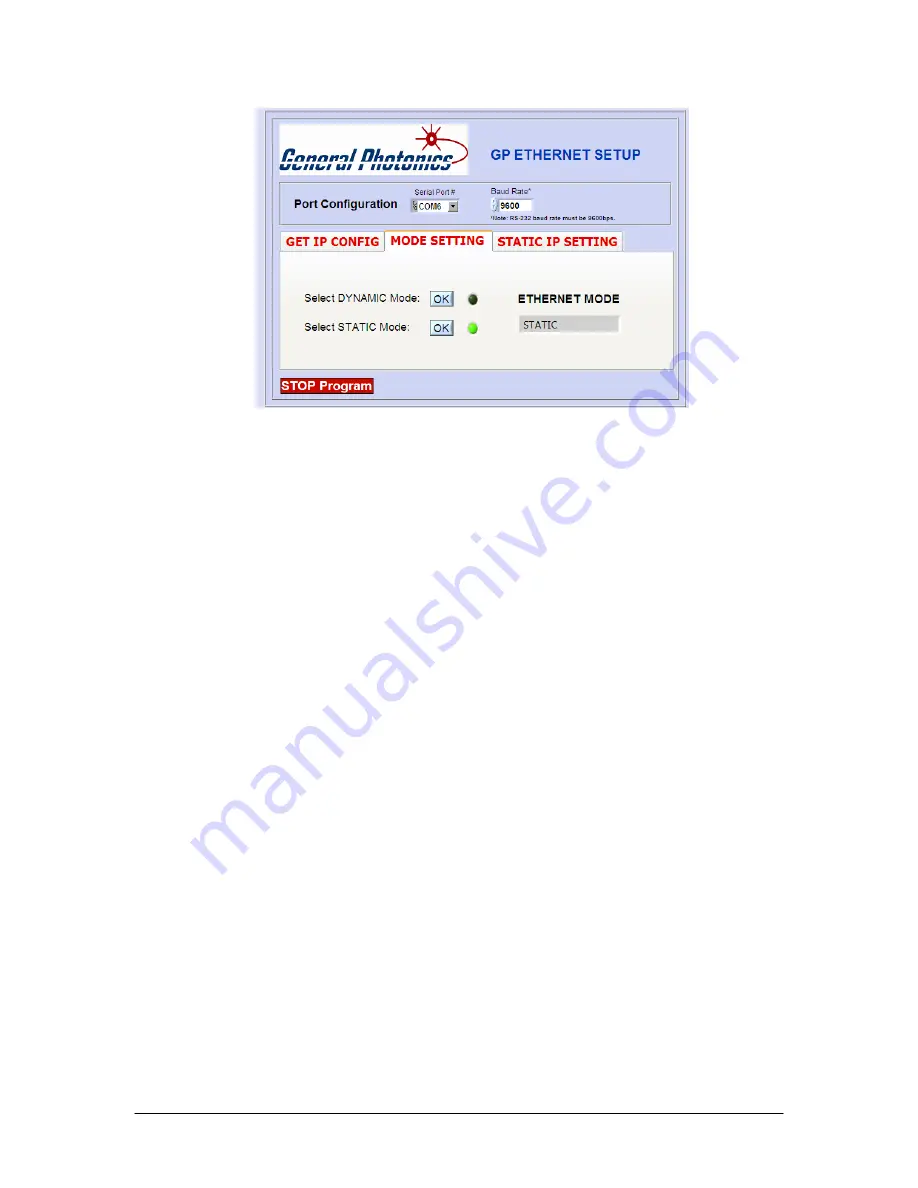
Ethernet mode selection screen- static
Clicking the “OK” button for dynamic mode puts the PDLE-101 into dynamic IP
mode. The instrument will obtain the dynamic IP information from the server. When
it is finished, the indicator for dynamic mode will turn green, and the Ethernet Mode
status box will say “DYNAMIC”.
Clicking the “OK” button for static mode puts the PDLE-101 into static IP mode. The
instrument will recall the static IP settings from its memory. These can then be used
for communication. When it is finished, the indicator for static mode will turn green,
and the Ethernet Mode status box will say “STATIC”.
The PDLE-101 writes its most recently saved static IP settings and its active mode to
memory. If it is powered off while in static mode, when it is powered back on, it will
be in static mode, and the most recently saved set of IP configuration information can
be used for communication.
If the PDLE-101 is powered off while in dynamic IP mode, when it is powered back
on, it will be in dynamic IP mode.
The third tab in the program, “STATIC IP SETTING”, allows the user to set the static
IP configuration information. Input the information into the corresponding boxes and
click the “SET” button. As each value is written, its indicator turns green. When all of
the information is successfully stored, the “Set OK” indicator will turn green.
Document #: GP-UM-PDLE-101-11
Page 45 of 61
Summary of Contents for PDLE-101
Page 31: ...3 Click Next 4 Click Next Document GP UM PDLE 101 11 Page 31 of 61 ...
Page 32: ...5 Check Specify a location then click Next Document GP UM PDLE 101 11 Page 32 of 61 ...
Page 36: ...12 Click Next 13 Click Finish Document GP UM PDLE 101 11 Page 36 of 61 ...
Page 38: ...In this example the USB device is connected to COM3 Document GP UM PDLE 101 11 Page 38 of 61 ...
Page 49: ... Properties on General tab Document GP UM PDLE 101 11 Page 49 of 61 ...


