background image

Maintenance

Inspections and preventive maintenance

7821-9001-005
01. October 2019

77 / 100

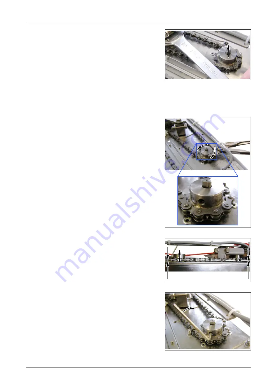
● Remove the sprocket from the drive

shaft.

● Replace any defective parts (e.g. chain or sprockets).

● Place sprocket with chain on the drive shaft, loosening the chain with the

spanner.

● Turn the sprocket until the threaded pin

is pointing towards the flat surface of the
drive shaft.

● Position the sprocket at the required

height on the drive shaft.

=

=

● Tighten the threaded pin on the

sprocket (drive) with a spanner.

● Re-assemble the sampling device.

Summary of Contents for DairyRobot R9500

Page 1: ...DairyRobot R9500 Automatic milking system Sampling device Operation Manual Installation Instructions Parts List Original operating instructions 7821 9001 005 01 October 2019 gea com ...

Page 2: ... Changes 12 3 3 Design of the equipment 13 3 4 How the System Works 15 3 5 Technical Data 20 4 Transport 21 4 1 Safety instructions for transport 21 4 2 Transport 22 4 3 Delivery 24 4 4 Storage conditions 24 4 5 Information on disposing of packing material 24 5 Sampling device 25 5 1 Special personnel qualification required for sampling 25 5 2 Safety instructions for sampling 25 5 3 Description of...

Page 3: ...tenance work 71 8 2 Safety instructions for maintenance 71 8 3 Inspections and preventive maintenance 73 9 Decommissioning 80 9 1 Safety instructions for decommissioning 80 9 2 Temporary decommissioning 80 9 3 Final decommissioning disposal 80 10 Spare Parts 81 10 1 Milk sampling device 81 10 2 Bottle racks 90 11 Appendix 92 11 1 Order of the sample bottles in the rack 92 11 2 Terminal diagram for...

Page 4: ...gy used in this manual are explained in greater detail in the Appendix These instructions are part of the supply They should be kept close at hand and remain with the equipment even if the equipment is sold This manual is not subject to an amendment service The most recent version at any time can be obtained through the technical dealer or directly from the manufacturer This manual has a modular s...

Page 5: ...05 01 October 2019 5 100 Necessary documents Instructions on components connected with the product not a complete list Part no Description 7821 90 000 DairyRobot R9500 operating instructions 7160 90 531 DairyManagementSystem DairyPlan C21 ...

Page 6: ...or section If a manual number is given the middle 4 digits indicate the language as follows Language Language Language 9000 German 9013 Dutch 9032 Serbian 9001 English United Kingdom 9015 English North American 9034 Slovak 9002 French France 9016 Polish 9035 Chinese 9003 Italian 9018 Japanese 9036 Lithuanian 9004 Romanian 9021 Danish 9038 Portuguese Brazil 9005 Spanish Spain 9022 Hungarian 9039 Fr...

Page 7: ...sary please contact your nearest authorized technical dealer There is a comprehensive dealer Internet search function on our website at the following address www gea com European Contact Information GEA Farm Technologies GmbH Siemensstraße 25 27 D 59199 Bönen 49 0 2383 93 70 49 0 2383 93 80 contact gea com www gea com US Contact Information GEA Farm Technologies Inc 1880 Country Farm Dr Naperville...

Page 8: ...nized standards in particular DIN EN ISO 12100 2011 03 Safety of machinery General principles for design Risk assessment and risk reduction DIN EN 61000 6 2 2011 06 Electromagnetic compatibility EMC Part 6 2 Generic standards Immunity for industrial environments DIN EN 61000 6 3 2011 09 Electromagnetic compatibility EMC Part 6 3 Generic standards Emission standard for residential commercial and li...

Page 9: ...he section on Basic Safety Instructions must be followed The legal requirements are observed Operating instructions must be developed for and specially adapted to the conditions of the farm to take account of all aspects of safety The product may only be used for its intended purpose The product may only be used if it is in perfect working condition The safety devices especially must be checked re...

Page 10: ...r your own safety read and follow the operating manual carefully especially the section entitled Safety information The chapter on Technical data gives the permissible working conditions pressure ranges temperature ranges airflow quantities etc and these must be observed Do not open or dismantle devices risk of injury Do not remove any protective devices risk of injury When working with cleaning a...

Page 11: ... the manual and then act accordingly Only use trained or briefed personnel In addition special qualifications are required for the following activities Installation Commissioning Operation Troubleshooting repairs Note Work that requires special qualifications is described in the relevant chapters 2 5 Safety guard and devices Cover plate protective cover Safety symbols warnings warning signs and la...

Page 12: ...ies not supplied by ourselves and setting instructions not provided by the manufacturer supplier are not checked or released by us either The installation or use of products from other manufacturers may affect the specified properties of the original parts and lead to injury to people and animals The manufacturer does not accept any liability for injury to people or animals or damage to the produc...

Page 13: ...tion the bottle rack correctly Bottle rack 80 x 15 ml to 35 ml sample bottles can be placed in different racks Sampling case This case contains all of the accessories for the sampling device Sample tank unit The sample tank is connected to the milk meter Once the milk sample has been collected air is let into the tank to mix the milk A sample is then taken from the tank through the sampling tube T...

Page 14: ...s Limit switch The limit switch stops the chain motor when the filling nozzle reaches the start position Electromagnetic crimp valve mixing valve When this valve is actuated the sample in the sample tank is mixed by atmospheric air Hose pump The pump pumps a small amount of milk into the drain channel to rinse the hose before the sample is placed in the sample bottle Chain motor Brings the nozzle ...

Page 15: ...15 100 3 4 How the System Works Milking system Sampling device 1 2 3 4 5 6 7 8 Legend 1 Sample tank 5 Hose pump 2 Stop balls 6 Filling nozzle 3 Air intake valve 7 Drain channel 4 Mixing valve 8 Sample bottle The following diagrams show how the sampling device works ...

Page 16: ...e During the milking process the sample tank is filled with about 2 5 of the actual milk produced After milking atmospheric air flows through the open mixing valve and mixes the sample in the sample tank 3 4 2 Draw sample The hose pump turning 100 draws the sample out of the sample tank ...

Page 17: ...21 9001 005 01 October 2019 17 100 3 4 3 Rinse lines with milk The hose pump turning 60 pumps the first part of the sample into the drain channel 3 4 4 Position filling nozzle The filling nozzle is positioned over the next sample bottle ...

Page 18: ...2019 18 100 3 4 5 Fill sample bottle The hose pump turning 60 fills the sample bottle with the sample 3 4 6 Drain lines atmospheric air flows in through the open mixing valve and drains the intake line The hose pump turning 60 100 also drains the pressure line ...

Page 19: ...r 2019 19 100 3 4 7 Return The filling nozzle is moved to the next drain position through one of the two drain channels 3 4 8 Drain sample tank Air flows into the sample tank through the open air inlet valve releases the stop balls and drains the sample tank ...

Page 20: ...00 3 5 Technical Data Geometric data Dimensions width x height x depth 650 x 530 x 240 Weight of the case without bottle rack 24 5 kg Electrical data Electrical Connection 24 V DC Manufacturer s plate The rating plate is placed on the side of the sampling device ...

Page 21: ...se should be carried or moved by two persons There are handles on both of the short sides Maintain a healthy posture when lifting and carrying Keep your spine straight study the illustration right wrong Attention The case contains sensitive items Do not throw it Always place the case on the floor gently 4 1 Safety instructions for transport Read the Safety section as well Special transport hazards...

Page 22: ...ning device The front drain channel in the wall of the box The sampling hose and connecting cable must be placed behind the positioning device in the box Attention Trapped lines The lines must not get trapped when the sampler is closed The plug on the connecting cable must be fed through the positioning device to the back Alternatively the plug may be fastened to the positioning device with a cabl...

Page 23: ...connecting cable or hose on top of the bottle rack The cable or hose might get dam aged when the sampling device is closed Attention Never leave the drain channels loose in the box Never leave the connecting cable plug loose in front of the positioning device This may cause damage to components hose pump hose etc when the sampler is closed or during transport ...

Page 24: ...ation instructions 4 Bottle rack to hold up to 80 sample bottles Option 4 4 Storage conditions It is recommended that the device is stored in a dry dust free and frost free environment Please note The sampling device should be kept clean to extend its service life 4 5 Information on disposing of packing material After unpacking the packing material must be handled properly and disposed of carefull...

Page 25: ... is a fault Read the Safety section as well Special risks involved in sampling Incorrect use may lead to serious damage to property and or life threatening injury to people Before taking samples ensure you are familiar with the operating and control elements The equipment included The method of operation The immediate surroundings Carry out the following checks before every start Check and make su...

Page 26: ...longing to the automatic milking system Milk sampling device T1 T2 L S Legend L Indicator lights On indicator green T1 RESET button Move filling nozzle to the start position T2 PUMP button Operate the hose pump manually S Selector switch Set sample quantity System computer System computer control panel user interface Operated by touching the screen See instructions for further information on the s...

Page 27: ...stem Take samples Start automatic operation Note the box data Interrupt sampling Stop automatic operation Stop sampling Change the bottle rack Resume sampling Resume automatic operation End sampling Stop automatic operation Stop sampling Create the sample file Transfer the sample bottles Start the system clean Disconnect and remove the sampling device Resume automatic operation 5 5 Prepare for sam...

Page 28: ...01 005 01 October 2019 28 100 5 5 1 Stop automatic operation Note The system waits until a wash or milking process that is still in progress ends before the milking box is blocked This can be seen from the graphic animation on the button LOCK BOX ...

Page 29: ...ugh the internal drain channels Set up the sampling device horizontally or with a slight incline Slope Set the sample quantity depends on the capacity of the sample bottles The correct volumes for filling the 15 ml to 35 ml bottles must be set with the selector switch Note The sample quantities actually filled may differ from the values given in the table They depend upon correct hose lengths vacu...

Page 30: ...0 Switch position 1 2 3 4 5 6 7 8 9 10 11 13 15 17 19 21 23 25 27 29 31 33 34 36 38 40 42 44 45 47 Sample quantity ml Set the switch as indicated in the table Note The capacity of the hose pump reduces over time This must be compensated for by increasing the switch setting ...

Page 31: ...installed 1 2 Attention Sample suction error If the ball catch 1 is not seated properly under the lid the balls do not block the holes in the lid properly when the sample is being sucked from the tank Check that the ball catch is seated properly 1 Loosen the nuts if necessary 2 Align the ball catch and retighten the nuts 1 2 Fit Y hose connectors ...

Page 32: ... Taper the intake tube at the bottom so that it cannot attach itself to the bottom of the tank Fit the hose and sealing ring to the intake tube so that the end of the hose cannot attach itself to the tank Place tank on the cover and fasten Note The arrow on the plug must be pointing up for sampling ...

Page 33: ...ank in the milking system Metatron The sample tank must be connected to the milk meter air inlet valve and sampling device To connect the sample tank remove the cover of the milking stall module and use the chain snap hook to hang it on the eye bolt of the end frame as shown 1 2 3 4 1 2 3 4 ...

Page 34: ... 9001 005 01 October 2019 34 100 Remove hose from the right hand connector on the sampler Fasten sample tank to the sampler with holder and knob Attention The hose and intake tube from the cover must end at the lowest point in the sample tank ...

Page 35: ...00 Connect the hose from the sample tank to the right hand connector on the sampler Fit the hose from the air inlet valve on the sample tank Connect the hose from the left hand connector on the sampler to the Y connector on the sampler Remove the cap from the sampler cover ...

Page 36: ...821 9001 005 01 October 2019 36 100 Connect the sampling tube on the sampling device to the sample tank Note The sampling device s operating times are adapted to the original length of the sampling hose Do not change the length of the hose ...

Page 37: ... drain channels must be fitted and a bottle rack inserted Push the front drain channel onto the side of the case Place the bottle rack in the positioning device Attention Make sure the bottle rack is the right way round Note numbering Note The bottle rack can only be inserted or removed without the rear drain channel fitted ...

Page 38: ...al rack number must be assigned If other rack numbers are to be used change them before starting sampling For information on this subject see the section entitled Stop sampling Attention Overheated samples The samples in the sampling device must not overheat Do not expose the sampling device to direct sunlight Note Keep the sample bottles filled with milk in a place that is cool and protected from...

Page 39: ... receives the electricity it needs from the automatic milking system Connect the 5 pole connector of the sampling case connection cable to the connector of the DairyRobot R9500 The green indicator lamp on the sampling device will light Press the RESET button The filling nozzle will be heard moving to the start position Close the sampler cover ...

Page 40: ...switch Sampling tab Start sampling START SAMPLING 2 To start sampling in MView Enter the following settings Number of sample bottles per bottle rack Number of samples per animal Boxes involved Number of the bottle rack The right hand screen must be filled out Sampling then starts and the status is shown on the Box page SAMPLING MODE 40 80 See instructions for further information on the subject 782...

Page 41: ...te after the cow has left the box before attaching the cluster to the next cow The sampling cycle does not start until the cluster has been removed and takes about one minute A message is generated when all of the sample bottles in the sampling device have been filled 5 6 2 Note the box data Note the following data so that the data export can be checked Sampling start time ID of the first cow in e...

Page 42: ...ce bottle rack Push rear drain channel onto the positioning device Press the RESET button the filling nozzle will be heard moving to the start position Close the sampler cover Enter the number of the new bottle rack Press the button for entering a new rack number Enter the rack number 5 7 3 Resume automatic operation Open the menu item Unlock box UNLOCK BOX ...

Page 43: ...OX Note The system waits until a wash or milking process that is still in progress ends before the milking box is blocked This can be seen from the graphic animation on the button LOCK BOX 5 8 2 Stop sampling Stop sampling Press the Stop button 5 8 3 Create the sample file Export sampling data For further information see section Sample data export ...

Page 44: ...same order when the data is exported Attention Incorrect sequencing when transferring the sample bottles to the laboratory unit can result in incorrect test results When transferring the sample bottles to the laboratory unit make sure that the same order also corresponds to the order of examination in the laboratory Open the sampler cover Transfer the sample bottles to the laboratory unit 1 1 2 2 ...

Page 45: ...is running Warning Risk of scalding Hot steam generated during the main system clean can cause scalding if the device cover is left open Do not open the cover during the main system clean Note It is not necessary to remove the bottle rack before the system clean begins Once sampling has been completed start a system clean to clean the sampling device Start system clean Note It is not necessary to ...

Page 46: ...g the device but in reverse order Note The sample tank unit remains with the sampling device It is used to carry out measurements on that sampling device To extend its service life the sampling device should be kept clean and it should be stored in a dry place at room temperature 5 8 7 Resume automatic operation Open the menu item Unlock box UNLOCK BOX Switch entry gates to all milking boxes to au...

Page 47: ...current sampling process 7821 9001 005 01 October 2019 47 100 Note The settings for a particular animal can be changed by pressing its animal number ANIMAL 123 Special features during sampling Take an extra sample Do not sample No special feature SAVE ...

Page 48: ...on hose should be disconnected from the lid of the sample tank at the end of the system clean and placed in a vessel containing hot water The pump in the sampling case should then be operated using the Pump button for about 1 minute to flush residual milk from the suction hose Also clean the sampling device manually inside and out after each session Never clean electrical equipment with water or s...

Page 49: ...ith ADR directive 1 2 and national DataDictionary AGRO2012 The Netherlands NL ADIS data in accordance with EDI Electronische Melkmeting EDI EMM Version 1 1 November 1998 and new issues France FR ADIS Data Entity 880022 Raw data There is a raw data export function for all other countries It uses a comma separated values text file csv that can for example be processed in a spreadsheet program The ex...

Page 50: ...M D program module has been purchased not obligatory for exporting sample data but necessary for importing milk control results exporting control messages etc Call up from the DP menu Datenaustausch LKV Kopplung Deutschland Data exchange LKV connection Germany Start the application DPMiko If it is not in the DPMenu start the program DPMiko exe directly from the DairyPlan installation folder with W...

Page 51: ...Sample data export To call up the program 7821 9001 005 01 October 2019 51 100 Start the application Robotermilchmengen_an_LKV based on DPRequest exe ...

Page 52: ... it is not possible to call up from the DP menu Alternatively a link file with the name lancer FR_Export_Donnees_Echantillonnage lnk is copied into the DairyPlan installation directory during installation This file can be dragged from the DairyPlan directory onto the desktop so that it can be used as a shortcut Call up the application from the link as follows DP Installationspfad DPRequest exe Exp...

Page 53: ...mple data export Open the SampleDataCSVExport rfa DairyPlan list from the DairyPlan folder to export the raw data Example C DairyPln FactOrig DE SampleDataCSVExport rfa 1 The following data must be entered milking parlour number sampling begin date sampling begin time sampling end date sampling end time 2 The displayed data can then be exported using the menu To do this open the File menu and then...

Page 54: ...uest application is started depending on the language set Germany DE Robotermilchmengendaten_an_LKV The Netherlands NL ExportMonstername France FR Export_Donnees_Echantillonnage The sequence is very similar Only the fields that have to be completed for the country in question are shown If no country specific sample data export is specified Use the raw data export ...

Page 55: ...ease note If samples were taken from all the animals in a herd these fields must be left empty Name of the target file The following are pre set DE DPADISproben ads NL MELKCTRL EMM FR Export_Donnees_Echantillonnage ads Please note The name can be changed and a path can also be entered Example A USB flash drive is displayed as drive E E DPADISproben090723 ads If a path is not entered the file will ...

Page 56: ...e relevant LKV or control centre if necessary Second farm name give the name that is to be included in the export data Postal code Town Address Telephone number Data centre code numbers and name are offered for the data centre Only the code number is included in the data If another data centre has to be given find the corresponding code number and enter directly in the field Laboratory code number...

Page 57: ...Sample data export Program execution 7821 9001 005 01 October 2019 57 100 Example DE Example NL Press the Next button Weiter to call up the next step ...

Page 58: ...milk yield test Test method who performed the test Test diagram usually S occasionally also special solutions which are not listed Test interval how often testing is performed Milking frequency always R for milking with a robot Note The exact details should be agreed with the relevant control centre Example DE Press the Next button Weiter to call up the next step ...

Page 59: ...umbers that come from other sampling operations for health monitoring for example and might confuse the control centre computer these data are exported in DairyPlan so that there are always zeros for the sample numbers Only the start of this time period date and time is entered this corresponds to the end of the previous sampling The end of the time period is calculated based on the start of the t...

Page 60: ... 7821 9001 005 01 October 2019 60 100 Example NL Example FR Attention Compare the bottle numbers The bottle numbers for the animals and the numbers on the bottles in the sample box must correspond Use the display screen to check carefully ...

Page 61: ...nt a sample data document Start the process by clicking on the corresponding button below date time of the sampling period Note The printed sample data document is added to the sample box or bottle rack and is sent with it to the laboratory The sender of the samples and the number of boxes and bottles can be taken from the printed document ...

Page 62: ... farms and is referred to as Entity 880033 by the data centres Note Not all computer centres can process this data for a milking robot Check in advance whether your data centre can read the data entity 880033 from a farm that uses robots Attention Data about dry animals and colostrum cows can only be created on the sampling day If data is reported at a later date omit the data entity 880033 becaus...

Page 63: ... to be exported general details of the farm or herd Click on the button DPList will open in a separate window Example DE Display data that are to be sent to the control centre as Entity 880001 Betriebsdaten farm data Example NL Display data that are to go to the control centre as Entity 204008 Gebeurtnis Bedrifsgegevens farm data and Entity 204010 Gebeurtnis Registratie list of animals on the farm...

Page 64: ...rresponding period Click on the button DPList will open in a separate window Example DE Displays data that are to be transmitted as Entity 880022 Einzelgemelke single milk output Note The ear marker numbers of all animals for which data will be exported must be clearly entered as a 15 figure number Example NL Display data that are to be transmitted as Entity 204250 Gebeurtnis Monstername Koe ...

Page 65: ...r the period after the end of the previous sampling This is important because unofficial samplings may interfere with the processing of the data in the laboratory The number of bottle numbers listed must be the same as the number of sample bottles filled Additional Data Milk Control button NL only For exporting data in Holland it is possible to mark individual conspicuous animals sick animals for ...

Page 66: ... is saved as described in the section on DPRequest application main dialogue Send the file to the relevant control centre 6 2 6 Creating raw data Open the SampleDataCSVExport rfa DairyPlan list from the DairyPlan folder to export the raw data Example C DairyPln FactOrig DE SampleDataCSVExport rfa 1 The following data must be entered milking parlour number sampling begin date sampling begin time sa...

Page 67: ... language in the order Day Month Year Time of milking time Quantity of milk from this milking yield The decimal marker point or comma is shown according to the language Box number rackNr Bottle number bottle Note The first row lists the abbreviated designations of the data fields The values are separated from each other by a semicolon Example cowNr earTag boxNr date time yield rackNr bottle 3 2760...

Page 68: ...fety Instructions for Troubleshooting To prevent damage to property and or life threatening injury to personnel the following must always be observed First of all prevent the product from being restarted accidentally Ensure that safe disconnection can be carried out by a second person at any time Read the Safety section as well Special dangers involved in troubleshooting If energy sources are swit...

Page 69: ...mple in the sample bottle Reducing hose pump capacity Sampling hose red is kinked Readjust the quantity with the switch Replace the hose of the hose pump Adjust the sampling hose until it is no longer kinked Air inlet hose for mixing is leaking Check and replace if damaged Suction hose red is caseated Disconnect the suction hose from the tank and hold it in a vessel containing hot water run the pu...

Page 70: ...ake valve is faulty Replace the air intake valve Samples are not being drawn from the sample tank Cable not connected Check the connecting cable connect properly if necessary At the beginning of sampling from a new cow residue from the suction hose flows back into the tank Residue from the previous sample remains in the suction hose The hose in the mixing valve is not opening completely when the l...

Page 71: ...manufacturers it cannot be ensured that they have been designed and produced from the point of view of loads and safety All of the steps involved in the maintenance work must be worked through in the order specified The maintenance work specified in the instructions adjustment cleaning lubrication inspection etc must be performed at the times specified Maintenance work should only be performed wit...

Page 72: ...avoid static caused for example by clothing On completion of the maintenance work check that The installation values set before the work was performed have not been changed by the work see settings report all screwed connections that were loosened earlier have been tightened All safety devices guards tank covers etc that were removed previously have been put back correctly All safety equipment is ...

Page 73: ...rts replace Filling position Check and adjust limit switch if necessary every 3 years 45000 60000 Chain driving pinion chain sprockets Check replace if necessary Hose pump replace Period of constant use several times a week Carry out regular checks on electrical equipment Tighten any loose connections Replace damaged lines or cables immediately Close off any cable openings that are not being used ...

Page 74: ... hose every year to ensure reliable operation Attention Only replace the hose when the hose pump is off Attention Only replace the hose when the hose pump is off Switch off the hose pump before replacing the hose Pull the hose out from the hose pump Undo the three screws in the housing cover Remove the housing cover form the hose pump ...

Page 75: ...ttention Not fitting the housing cover properly can damage the hose or cause fluctuation of the pump output Make sure that the housing cover is positioned correctly between the guide marks x The housing cover must be flush x Reconnect the hoses to the outside of the hose pump The pump can now be used again Note After replacing the hose reset the sample quantities required on the unit and carry out...

Page 76: ...ed for several years Warning Danger from automatic start The conveyor chain can start to move when work is being carried out There is a risk of crushing and electric shock Disconnect the cable from the power supply before starting the work Undo the four screws holding the sampling equipment in the lid Turn the sampling equipment out of the lid so that the chain is on top Loosen the threaded pin on...

Page 77: ...e g chain or sprockets Place sprocket with chain on the drive shaft loosening the chain with the spanner Turn the sprocket until the threaded pin is pointing towards the flat surface of the drive shaft Position the sprocket at the required height on the drive shaft Tighten the threaded pin on the sprocket drive with a spanner Re assemble the sampling device ...

Page 78: ...ct the cable to the automatic milking system Press the RESET button The filling nozzle will be heard moving to the start position Open the catch on the top of the cover Briefly press the button on the right of the electronic card The filling nozzle moves one position further Check the nozzle s first filling position The filling positions are marked by notches Press the RESET button The filling noz...

Page 79: ...ic start The conveyor chain can start to move when work is being carried out There is a risk of crushing and electric shock Disconnect the cable from the power supply before starting the work Take the sampling device out of the lid as described in Replacing the chain and sprocket and turn over The limit switch is accessible Change the position of the limit switch so that the filling nozzle is exac...

Page 80: ...ssioning Leaking lubricants solvents preservatives can cause injury if they come into direct contact with the skin Components which have not been removed correctly may fall off or twist Exposed sharp edged components tools may cause injury 9 2 Temporary decommissioning Stop sampling To extend its service life the sampling device should be kept clean and it should be stored in a dry place at room t...

Page 81: ...terrior 0080 7800 0025 657 Cover holder 0090 7800 0025 663 Distance bush M8x56 0100 0019 6901 300 Hexagon head bolt M8x16 0120 0026 0439 300 washer 8 4x24x2 0130 7800 0025 678 Lock washer 7 0150 7801 1268 020 Drain channel welded Duo Compact II 0160 7801 1268 000 Drain channel welded rear 0170 0019 9100 300 Cheesehead screw M4x16 0180 0026 0429 300 washer 5 3x15x1 2 0190 0026 1362 300 washer 4 3 0...

Page 82: ...ilable by the metre 0060 7021 7106 058 x Milk hose silicone 8 5x3 75 x25 000 Sil gn 0070 7021 7106 050 8 5x3 75x225 Sil gn 0160 0018 5324 820 Y hose connector 10 0170 7021 7106 058 Milk hose silicone 110 mm 8 5x3 75 x25 000 Sil gn 0180 7021 7106 058 Milk hose silicone 120 mm 0190 0026 2249 890 Cap 4x15 0200 0007 1974 700 Sealing ring 10x2 x Wear part see section on Maintenance for maintenance inte...

Page 83: ...g ring 9x2 0070 0013 0311 300 Hexagon Head Nut M5 0090 7821 2084 230 Bracket 93 1x114 3x20 T3 0100 7161 6708 000 Plug complete ø12 Metatron with 110 130 0110 0007 2509 700 x Sealing ring 8x2 0120 0026 1508 890 Ball 12mm 0130 0007 1974 700 x Sealing ring 10x2 0150 0013 0276 300 Hexagon Head Nut M6 0160 7801 4807 000 connector RMS 0170 7051 2045 000 hose connector 7821 9905 030 Set of spare parts x ...

Page 84: ... 40 Item Part no Description 7161 3270 000 Clip complete 0010 7161 2097 140 Clamp øo69x17 0020 7161 2653 000 Clamp 55xø4 0040 0007 3239 890 x Sealing ring 25 Tri Clamp øo50 5xøi25 3 x Wear part see section on Maintenance for maintenance interval Included in set of spare parts 7821 9905 030 ...

Page 85: ...7161 1467 000 Sealing panel 36x20xD4 0060 0007 2060 700 Sealing ring 66 x 6 0070 0007 1818 700 Sealing ring 9 x 2 0080 7021 7106 058 Milk sampler hose silicone 8 5x3 75 x25 000 Sil gn 210 mm 0090 7021 7106 058 Milk sampler hose silicone 8 5x3 75 x25 000 Sil gn 110 mm 0100 7021 7106 058 Milk sampler hose silicone 8 5x3 75 x25 000 Sil gn 120 mm 0110 0018 4376 898 tube ID4xOD7 xL25 000 Sil tp 160 mm ...

Page 86: ...0 0025 633 Shaft ø12x19 5 0040 7801 2160 000 Cover complete 0050 7801 5566 000 Lever 0060 7801 6915 000 Tensioner 0070 7801 5300 000 Drive unit 0080 0005 3301 000 Sub unit terminal block MSTB2 5 2 ST 5 08 0090 0005 3302 000 Sub unit terminal block MSTB2 5 3 ST 5 08 0100 7800 0025 646 V Ring ø22 0110 7801 5847 010 Limit switch complete 0120 7800 0025 647 x Connector complete ø5 0130 0013 0310 300 H...

Page 87: ...A AK QB 0500 0004 3079 828 Sealing strip 9x2 0510 7801 6933 010 Cable complete Connection 0520 7801 6933 020 Cable complete Hose pump 0550 7800 0025 601 Support buffer 20x40x45 0560 7800 0025 609 x Sprocket Drive unit 0580 7800 0007 492 Distance bush M4x35x9 0590 0019 6077 300 cylindrical head screw M4x10 0600 0026 1362 840 washer 4 3 0610 0013 0310 300 Hexagon Head Nut M4 0620 0019 6910 300 Hexag...

Page 88: ...00 x tube 0020 7801 4900 000 x Spare Parts Housing cover and hose 0030 7015 9902 200 x Set of spare parts x Wear part see section on Maintenance for maintenance interval Illuminated pushbutton complete 10 20 Item Part no Description 0005 3768 880 Illuminated pushbutton complete green 0010 0005 1312 900 Indicator lights 0020 0005 1343 910 Diaphragm green ...

Page 89: ...e complete 60 30 70 40 Item Part no Description 7801 6933 010 Cable complete Connection 0030 0005 1773 040 Connector housing HAN 3A M20 0040 0005 4486 900 Cable Screw Joint M16x1 5x5 10 0060 0005 4465 900 reduction M20x1 5 M16x1 5 0070 0005 1773 030 Connector insert HAN 4A M ...

Page 90: ... Spare Parts Bottle racks 7821 9001 005 01 October 2019 90 100 10 2 Bottle racks 7821 6451 000 9000 7821 6451 010 9000 7821 6451 020 9000 7821 6451 030 9000 7821 6451 040 9000 ...

Page 91: ...000 7821 6451 070 9000 Item Part no Description 9000 7801 6451 000 Bottle rack DE CH JP PL 7801 6451 010 Bottle rack NL new USA 7801 6451 020 Bottle rack NL old 7801 6451 030 Bottle rack SE 7801 6451 040 Bottle rack DK 7801 6451 050 Bottle rack FR LT 7801 6451 070 Bottle rack NO ...

Page 92: ... in the rack 7821 9001 005 01 October 2019 92 100 11 Appendix 11 1 Order of the sample bottles in the rack Legend Sample bottle number Order in which the sample bottles are filled Milking box numbering Left hand version Right hand version ...

Page 93: ...rminal diagram for the CUP electronic card 7801 9047 030 1 2 3 4 Legend 1 Valve 2 pump 3 Motor 4 Limit switch 11 3 Pin assignment Legend UB 24V voltage monitoring OUT SC Sample Clean Signal IN PE Earth green yellow Protection Earth 1 Electrical Requirements 2 dimensions ...

Page 94: ... are separated by a comma or similar symbol Comma Separated Values DP Herd management program DairyPlan LKV Landeskontrollverband National control association Germany MLP Milk yield test MView Milking system user interface Ø Diameter øi Inside Diameter øo O D outside diameter Percentage Units degrees angles C Degrees Celsius Centigrade s Second in inch 25 4 mm mm Millimetres m meters kg Kilogram k...

Page 95: ...5 Quick guide 11 5 1 Start sampling Stop automatic operation Open the menu item Lock box LOCK BOX Wait until the animals have left the milking boxes Set up and connect the sampling device Set up the sampling device Place the bottle rack in the positioning device ...

Page 96: ...the sampling device to the sample tank Connect the cable to the automatic milking system Connect the 5 pole connector of the sampling case connection cable to the connector of the DairyRobot R9500 The green indicator lamp on the sampling device will light Press the RESET button The filling nozzle will be heard moving to the start position ...

Page 97: ...r of sample bottles per bottle rack Number of samples per animal Boxes involved Bottle rack number Enter the rack number Starting sampling on the Mview The following settings are possible Unlocking the milking box Open the menu item Unlock box UNLOCK BOX Note the box data Note the following data so that the data export can be checked Sampling start time ID of the first cow in each box ...

Page 98: ...ft the milking boxes Stop sampling Stop sampling SAMPLING MODE 40 80 Create the sample file Export sampling data For further information see section Sample data export Start the system clean Start system clean Disconnect and remove the sampling device Carry out the steps described for setting up and connecting the device but in reverse order Resume automatic operation Unlocking the milking box Ope...

Page 99: ...Appendix Quick guide 7821 9001 005 01 October 2019 99 100 ...

Page 100: ...Ê 49 0 2383 93 80 gea com We live our values Excellence Passion Integrity Responsibility GEA versity GEA Group is a global engineering company with multi billion euro sales and operations in more than 50 countries Founded in 1881 the company is one of the largest providers of innovative equipment and process technology GEA Group is listed in the STOXX Europe 600 index ...

Reviews:

Related manuals for DairyRobot R9500