RCL220_manual_v3-draft.doc
05-XXXXA01 Version 3 Draft
Page 26 of 79
9/20/2016
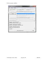
In the example screenshot above, you can see that the radio is “Currently executing” application
image 2, which is 3.9.34. The DSP and MCU versions are also reported, and these are typically
different than the application image version.
3.1.3
Test Polling
Frequently it is desired to send and receive test messages between radios on the bench. To do this
test, you will require two PRMs, power supplies, serial connectivity, RF cables and RF attenuators to join
the radios’ antenna ports, and the Poller and Responder utilities to simulate the LCU and OCU for
sending and receiving messages.
BEWARE: Do not simply cable the two radios together or you may damage one or both of the
receivers. Use at least 90 dB of attenuation between radios.
Alternately, you can poll over the air with suitable antennas, however you may not achieve 100%
message success rate using this method.
1.
Set up the Polling device as the LCR as shown below:
Summary of Contents for MDS RCL220
Page 19: ...RCL220_manual_v3 draft doc 05 XXXXA01 Version 3 Draft Page 19 of 79 9 20 2016 ...
Page 20: ...RCL220_manual_v3 draft doc 05 XXXXA01 Version 3 Draft Page 20 of 79 9 20 2016 ...
Page 21: ...RCL220_manual_v3 draft doc 05 XXXXA01 Version 3 Draft Page 21 of 79 9 20 2016 ...
Page 22: ...RCL220_manual_v3 draft doc 05 XXXXA01 Version 3 Draft Page 22 of 79 9 20 2016 ...
Page 23: ...RCL220_manual_v3 draft doc 05 XXXXA01 Version 3 Draft Page 23 of 79 9 20 2016 ...


