RCL220_manual_v3-draft.doc
05-XXXXA01 Version 3 Draft
Page 10 of 79
9/20/2016
12
11
10
9
8
7
6
5
4
3
2
1
24
23
22
21
20
19
18
17
16
15
14
13
25
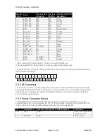
2.1.3
Power Connector Pinout
The Access Point provides a Phoenix 17 76 69 2 connector for DC power in. A surge protection device
such as a Polyphaser IS-17VDC-30A-NG capable of limiting the voltage input to the radio to less than
30 Volts should be employed.
Pin
Signal Name
Direction with respect to MDS Equipment
Description
1 (L)
PWR
Input
10 to 30 VDC input,
125 mA at 13.8 VDC
2 I
GROUND
Input
Power return.
2.2
entraNET 220 OEM Radio Module
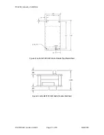
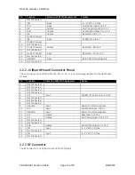
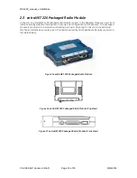
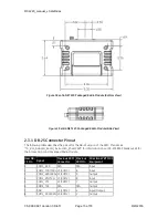
This unit is used in each OCU. It is a two-board solution (as shown below) that mates with RCL vendor
OCU hardware. Mechanical diagrams are provided below as well. The interfaces used by OEM Radio
Modules are listed in the tables below.
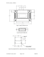
Figure 10 entraNET 220 OEM Radio Module (SMB Connector Not Shown)
Summary of Contents for MDS RCL220
Page 19: ...RCL220_manual_v3 draft doc 05 XXXXA01 Version 3 Draft Page 19 of 79 9 20 2016 ...
Page 20: ...RCL220_manual_v3 draft doc 05 XXXXA01 Version 3 Draft Page 20 of 79 9 20 2016 ...
Page 21: ...RCL220_manual_v3 draft doc 05 XXXXA01 Version 3 Draft Page 21 of 79 9 20 2016 ...
Page 22: ...RCL220_manual_v3 draft doc 05 XXXXA01 Version 3 Draft Page 22 of 79 9 20 2016 ...
Page 23: ...RCL220_manual_v3 draft doc 05 XXXXA01 Version 3 Draft Page 23 of 79 9 20 2016 ...


