


APPLICATION NOTES
17-2
MIF Digital Feeder Protection
GEK-106273L
This recloser can be configured to:
* Once in Lockout, wait for an operator to go and reset the Logic, pushing the button on the front of the MIF relay.
* Automatically reset when the operator closes the breaker.
In the logic drawn above, the option chosen is the automatic reset one. This is done by configuring INPUT#1 as
status of the breaker (52b) and to RESET the latched outputs, in this case, the LOCKOUT output. While this output is
active, it blocks the operation of the logic.
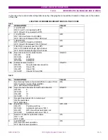
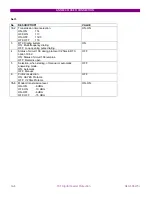
17.1.1. I/O
CONFIGURATION
Output#1 (B7)
:
TRIP
.
Output#2 (B8)
:
CLOSE
. This signal comes from the
LOGIC#2
.
Output#3 (B9)
:
LOCKOUT
. This signal comes from
LOGIC#4
and it can be set in two different ways:
A. Latched, so the operator must manually close the breaker and also reset the recloser.
B. We can program the relay to automatically leave the LOCKOUT status as soon as the operator manually
closes the breaker.
INPUT#1 (A8)
: it receives the
52b
signal of the breaker. If we want the recloser to automatically reset from the
LOCKOUT status when the operator closes the breaker, then we will configure INPUT#1 as
52b plus RESET
(inverted) of latched outputs. The relay must reset latched outputs when breaker is closed, i.e. when voltage is
removed from the 52b input, this is why RESET appears as inverted.
INPUT#2 (A9)
: it receives the
Reclose Block
signal, plus the
LOCKOUT
(output B9), connected in parallel. When
this input is active, either because the operator activates the input, e.g. using any key, to block the 79, either
because the 79 goes to lockout after reclosing and trip (only 1 shot is allowed), the reclose logic is blocked.
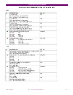
17.1.2. LOGIC
CONFIGURATION
LOGIC#1:
When the breaker is open, the logic does not work, as the logic needs the 52b signal OFF to start. (first AND in
LOGIC#1).
When the breaker is closed, if there is a fault and the relay trips, and if the INPUT#2 is off, meaning that there is no
external block and the 79 is not in lockout, then the LOGIC is started.
LOGIC#1 converts the TRIP signal into a pulse, wide enough to serve as input to the timer which counts the reclosing
time (dead time) in LOGIC#2. This conversion is done by the TIMER in logic 1, using a drop-out time of 3 seconds.
We call Recloser Initiation to this signal.
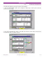
LOGIC#2:
The Reclose Initiation signal (LOGIC#1) goes into an AND gate in LOGIC#2.
This AND operates if this signal is active, the breaker is open (after the trip), there is no block or lockout and no trip
condition for the reclosing time, set to 3 seconds. As there are only three possible inputs to the AND gate, we group
two of the four conditions (breaker open and no block/lockout) in an OR gate, using the Morgan rules to convert the
AND to an OR:
A9
A8
A9
A8
+
=
×
.
After the timer, we have the CLOSE signal, which is configured to output B8.
Summary of Contents for GEK-106273L
Page 19: ...GETTING STARTED 1 12 MIF Digital Feeder Protection GEK 106273L ...
Page 95: ...SETTINGS 5 38 MIF Digital Feeder Protection GEK 106273L ...
Page 101: ...I O CONFIGURATION 6 44 MIF Digital Feeder Protection GEK 106273L ...
Page 127: ...KEYPAD AND DISPLAY 8 26 MIF Digital Feeder Protection GEK 106273L ...
Page 147: ...INSTALLATION AND MAINTENANCE 10 2 MIF Digital Feeder Protection GEK 106273L ...
Page 199: ...ANNEX 5 HARMONIC FILTERING 15 4 MIF Digital Feeder Protection GEK 106273L ...