9-10
D30 Line Distance Protection System
GE Multilin
9.1 DISTANCE ELEMENTS
9 THEORY OF OPERATION
9
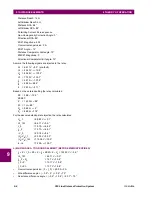
I_0
×
Z
D
= 1.37 V
∠
19.8°
I
A
×
Z
R
+ I_0
×
K0
×
Z
R
+ I
G
×
K0M
×
Z
R
– V
A
= 87.6 V
∠
–109.2°
I
A
×
Z
R
+ I_0
×
K0
×
Z
R
= 91.5 V
∠
–93.0°
I
A
×
Z
L
+ I_0
×
K0
×
Z
L
+ I
G
×
K0M
×
Z
L
– V
A
= 57.0 V
∠
108.7°
I
A
×
Z
L
+ I_0
×
K0
×
Z
L
= 45.8 V
∠
82.9°
•
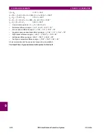
Overcurrent supervision: | 3
×
I_0 | = 4.09 A
>
3 A
•
Reactance difference angle = | –3.9° – 24.8° | = 28.7°
<
75°
•
Zero-sequence difference angle = | –19.8° – 0.0° | = 19.8°
<
75°
•
Negative-sequence directional difference angle = | –19.8° – 0.0° | = 19.8°
<
75°
•
Right blinder difference angle = | –93.0° – (–109.2°) | = 16.2°
<
90°
•
Left blinder difference angle = | 82.9° – 108.7° | = 25.8°
<
90°
•
Fault-type comparator difference angle = | 19.8° – 19.8° | = 0.0°
<
50°
All six comparators and the overcurrent supervision are satisfied.
The Quad Phase A ground element will operate for this fault.
Summary of Contents for D30D00HCHF8AH6AM6BP8BX7A
Page 10: ...x D30 Line Distance Protection System GE Multilin TABLE OF CONTENTS...
Page 374: ...5 248 D30 Line Distance Protection System GE Multilin 5 10 TESTING 5 SETTINGS 5...
Page 398: ...6 24 D30 Line Distance Protection System GE Multilin 6 5 PRODUCT INFORMATION 6 ACTUAL VALUES 6...
Page 410: ...7 12 D30 Line Distance Protection System GE Multilin 7 2 TARGETS 7 COMMANDS AND TARGETS 7...
Page 444: ...9 24 D30 Line Distance Protection System GE Multilin 9 5 FAULT LOCATOR 9 THEORY OF OPERATION 9...
Page 576: ...B 102 D30 Line Distance Protection System GE Multilin B 4 MEMORY MAPPING APPENDIX B B...
Page 616: ...D 10 D30 Line Distance Protection System GE Multilin D 1 IEC 60870 5 104 PROTOCOL APPENDIX D D...
Page 628: ...E 12 D30 Line Distance Protection System GE Multilin E 2 DNP POINT LISTS APPENDIX E E...
Page 636: ...F 8 D30 Line Distance Protection System GE Multilin F 3 WARRANTY APPENDIX F F...
Page 646: ...x D30 Line Distance Protection System GE Multilin INDEX...


