


GE Multilin
D30 Line Distance Protection System
1-11
1 GETTING STARTED
1.3 ENERVISTA UR SETUP SOFTWARE
1
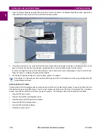
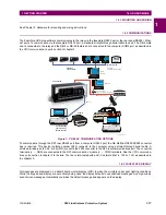
Next, use an Ethernet cross-over cable to connect the computer to the rear Ethernet port. In case you need it, the figure
shows the pinout for an Ethernet cross-over cable.
Figure 1–6: ETHERNET CROSS-OVER CABLE PIN LAYOUT
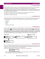
Now, assign the computer an IP address compatible with the relay’s IP address.
1.
From the Windows desktop, right-click the
My Network Places
icon and select
Properties
to open the network con-
nections window.
2.
Right-click the
Local Area Connection
icon and select
Properties
.
842799A1.CDR
END 1
END 2
Pin
Wire color
Diagram
Pin
Wire color
Diagram
1
White/orange
1
White/green
2
Orange
2
Green
3
White/green
3
White/orange
4
Blue
4
Blue
5
White/blue
5
White/blue
6
Green
6
Orange
7
White/brown
7
White/brown
8
Brown
8
Brown
1
2
3
4 5 6
7
8
Summary of Contents for D30D00HCHF8AH6AM6BP8BX7A
Page 10: ...x D30 Line Distance Protection System GE Multilin TABLE OF CONTENTS...
Page 374: ...5 248 D30 Line Distance Protection System GE Multilin 5 10 TESTING 5 SETTINGS 5...
Page 398: ...6 24 D30 Line Distance Protection System GE Multilin 6 5 PRODUCT INFORMATION 6 ACTUAL VALUES 6...
Page 410: ...7 12 D30 Line Distance Protection System GE Multilin 7 2 TARGETS 7 COMMANDS AND TARGETS 7...
Page 444: ...9 24 D30 Line Distance Protection System GE Multilin 9 5 FAULT LOCATOR 9 THEORY OF OPERATION 9...
Page 576: ...B 102 D30 Line Distance Protection System GE Multilin B 4 MEMORY MAPPING APPENDIX B B...
Page 616: ...D 10 D30 Line Distance Protection System GE Multilin D 1 IEC 60870 5 104 PROTOCOL APPENDIX D D...
Page 628: ...E 12 D30 Line Distance Protection System GE Multilin E 2 DNP POINT LISTS APPENDIX E E...
Page 636: ...F 8 D30 Line Distance Protection System GE Multilin F 3 WARRANTY APPENDIX F F...
Page 646: ...x D30 Line Distance Protection System GE Multilin INDEX...


