


GE Multilin
D30 Line Distance Protection System
5-75
5 SETTINGS
5.2 PRODUCT SETUP
5
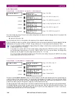
EXAMPLE 3: PILOT-AIDED SCHEMES
Consider the three-terminal line protection application shown below:
Figure 5–17: THREE-TERMINAL LINE APPLICATION
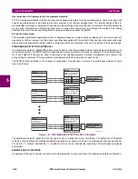
A permissive pilot-aided scheme could be implemented in a two-ring configuration as shown below (IEDs 1 and 2 constitute
a first ring, while IEDs 2 and 3 constitute a second ring):
Figure 5–18: SINGLE-CHANNEL OPEN LOOP CONFIGURATION
In the above application, the following settings should be applied. For UR-series IED 1:
DIRECT OUTPUT DEVICE ID:
“1”
DIRECT I/O CH1 RING CONFIGURATION:
“Yes”
DIRECT I/O CH2 RING CONFIGURATION:
“Yes”
For UR-series IED 2:
DIRECT OUTPUT DEVICE ID:
“2”
DIRECT I/O CH1 RING CONFIGURATION:
“Yes”
DIRECT I/O CH2 RING CONFIGURATION:
“Yes”
For UR-series IED 3:
DIRECT OUTPUT DEVICE ID:
“3”
DIRECT I/O CH1 RING CONFIGURATION:
“Yes”
DIRECT I/O CH2 RING CONFIGURATION:
“Yes”
In this configuration the following delivery times are expected (at 128 kbps):
IED 1 to IED 2: 0.2 of power system cycle;
IED 1 to IED 3: 0.5 of power system cycle;
IED 2 to IED 3: 0.2 of power system cycle.
In the above scheme, IEDs 1 and 3 do not communicate directly. IED 2 must be configured to forward the messages as
explained in the
Inputs and outputs
section. A blocking pilot-aided scheme should be implemented with more security and,
ideally, faster message delivery time. This could be accomplished using a dual-ring configuration as shown below.
842713A1.CDR
UR IED 1
UR IED 2
UR IED 3
842714A1.CDR
UR IED 1
TX1
RX1
UR IED 2
RX2
TX2
RX1
TX1
UR IED 3
RX1
TX1
Summary of Contents for D30D00HCHF8AH6AM6BP8BX7A
Page 10: ...x D30 Line Distance Protection System GE Multilin TABLE OF CONTENTS...
Page 374: ...5 248 D30 Line Distance Protection System GE Multilin 5 10 TESTING 5 SETTINGS 5...
Page 398: ...6 24 D30 Line Distance Protection System GE Multilin 6 5 PRODUCT INFORMATION 6 ACTUAL VALUES 6...
Page 410: ...7 12 D30 Line Distance Protection System GE Multilin 7 2 TARGETS 7 COMMANDS AND TARGETS 7...
Page 444: ...9 24 D30 Line Distance Protection System GE Multilin 9 5 FAULT LOCATOR 9 THEORY OF OPERATION 9...
Page 576: ...B 102 D30 Line Distance Protection System GE Multilin B 4 MEMORY MAPPING APPENDIX B B...
Page 616: ...D 10 D30 Line Distance Protection System GE Multilin D 1 IEC 60870 5 104 PROTOCOL APPENDIX D D...
Page 628: ...E 12 D30 Line Distance Protection System GE Multilin E 2 DNP POINT LISTS APPENDIX E E...
Page 636: ...F 8 D30 Line Distance Protection System GE Multilin F 3 WARRANTY APPENDIX F F...
Page 646: ...x D30 Line Distance Protection System GE Multilin INDEX...


