GEI-50299 Power Circuit Bre akers Types AK-2-15 and A K-2/3-25
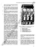
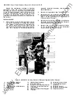
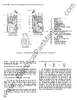
stationary contacts and be sure to locate them
in the breaker with the upper and lower contacts
having their stop projecting surfaces as shown
in the section
AA,
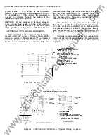
Figure 3 . The uppe r left
and lower right contacts are identical as are
the lower left and upper right contacts.
3 . By placing the hook o n the end of the contact
through the loop of the contact spring, the con
tact can be pushed toward the pivot surface
and slipped behind the stop pin. Install all
stationary contacts in all poles .
3 --
/�
9----..../
II
21
FRONT
VIEW
OF
STATIONARY CONTACTS
&
SPRINGS
AK-2-25
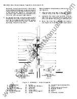
Figure 3 . (54 9D409-2 )
1 . B reaker Base
8.
Spring
REP LACE MENT OF MOVAB LE C ONTACTS
( 1 8 ) Figure 3.
1 . Coat the pivot area only of the new movable
contacts with a thin coat of D50H4 7 grease.
2 . Assemble the center pole movable contacts,
align the pivot pin holes with the bullet nosed
rod, and install the pivot pin and split pin.
3.
Move the c ross bar assembly into position
and insert the eccentric contact wipe adjust-
FRONT
VIEW
OF
STATIONARY CONTACTS
&
SPRINGS
AK-2-15
Contact Assembly
SECTION B-B
2 . Insulation
3 . Insulated Stud
9. Spring Clip ( Retainer)
1 5 . Contact Wipe Adjustment Pin
1 6. Screw
4.
Upper Stud Barrier
10.
Cross Bar
1 1 . Pivot Pin
17 . Upper Stud
&
Arc Runner
1 8 . Movable Contact
5 . Insulation
6.
Links (Insulated)
7 . Tie Bolt
1 2 .
Lower Stud
13. Contact Pivot Support
14. Spring
1 9. Spring
20. Nut
2 1 . Stationary Contacts
1 0
•
www
. ElectricalPartManuals
. com


